Display Modes
Features and Tools > Graphics > Display Modes
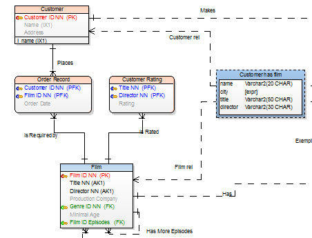
In Toad Data Modeler, you can switch between Logical (Captions), Physical (Names) and Full Names view of object names.
Select the display mode on Display Toolbar or in View Menu | Display Mode.
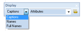
Logical View (Captions)
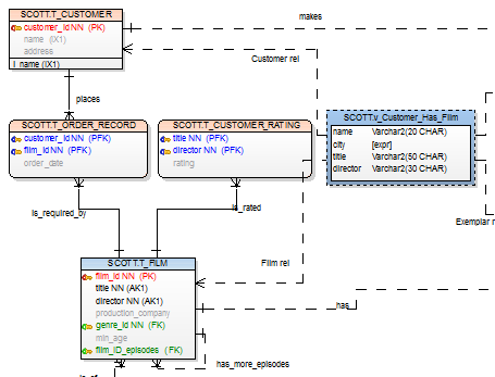
Physical View (Names)

Full Names
Display Level for Entities
Features and Tools > Graphics > Display Level for Entities
Toad Data Modeler allows you to display entities on Workspaces in several levels:
PER Model
- Entities
- Primary Keys
- PK and FK keys
- All Keys
- Attributes
LER Model
- Entities
- Primary Identifiers
- Unique Identifiers
- Attributes
- Descriptions - Text written in the Description tab of entity will be displayed on the WS.
To set the default display level for the selected Workspace
Change the display level from the Display Level box on the toolbar (also View | Display Level).
To set the default display level for new model (models that you will create)
Select Settings | Options | Physical/Logical Model | Entity tab.
Format Workspaces and Objects
Features and Tools > Graphics > Format Workspaces and Objects
You can set format for all Workspaces of your model, for each Workspace separately and also for particular objects.
To set format for new models (models that you will create)
- Select Settings | Options | Model section | Physical/Logical Model.
- Define options on tabs Workspace, Shape, Note Line and Entity.
- Press CTRL+N to create a new model.
To change format of objects in existing models
Right-click the Workspace and select Workspace Format.
To change format of a particular object
Right-click the object on the Workspace and select Format.
|

|
Note: If you need to preserve format of a particular object against changes of format of your WS, select the Lock Format option in the Object Format dialog | General tab. |
Line Autolayout
Features and Tools > Graphics > Line Autolayout
Toad Data Modeler provides you with an useful tool that is capable of automatically organizing your lines in your model diagram.
How to use Line Autolayout
- On workspace select lines which you want to organize (or don't select any to organize all lines).
- Go to Layout Menu | Line Autolayout or click
 on Layout Toolbar.

- Line Autolayout dialog displays. You can now customize its settings.
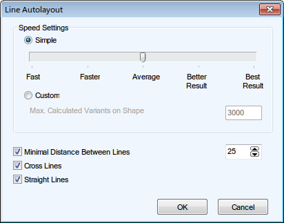
| Speed Settings |
Line Autolayout function tries to find the most optimal result from a set generated number of line variations. Generally, the more variants, the better the result and the more time Line Autolayout takes.
You can select the Simple option and use the slider to set the number of generated variations. Or select the Custom option and enter the maximum number of calculated variants manually.
Note that the bigger the number of variants and shapes on workspace is, the more time the process takes. |
| Minimal Distance Between Lines |
Determines the distance between lines on a shape edge. |
| Cross Lines |
When checked, variants where lines are crossed are preferred. |
| Straight Lines |
When checked, variants where lines are straight are preferred. |
Line Autolayout settings
Go to Settings Menu | Options | Graphics | Autolayout tab.

In Lines | Autolayout section you can define the default settings of Line Autolayout function.
