Capabilities
Business Process Modeling Notation (BPMN)
BPMN allows Agile EA to provide a notation that is usable and understandable by all business users, to communicate real-world process representations, to different interested stakeholders. The end results are business process models that allow a business to
Document and understand their internal business processes in a consistent, graphical manner
Be more agile and efficient, with increased visibility into its underlying processes
Understand how different business organizations interact and collaborate within internal procedures
Communicate the processes in a technical and non-technical manner to a wide audience
The processes can also be connected into the overall enterprise architecture, giving increased visibility of business context and understanding, as inputs into decision making and architectural change.
BPMN depicts these four element types for Business Process Diagrams:
1.Flow objects: events, tasks and gateways
2.Connecting objects: sequence flow, message flow, data association
3.Swim lanes: pool or lane
4.Artifacts: data object and data storage
Flow Objects Supported
|
Name |
Options |
Images |
Description | ||
|
Event |
Trigger |
Start |
Intermediate |
End |
|
|
|
None |
|
|
|
An Event is something that “happens” during the course of a Process. These Events affect the flow of the model and usually have a cause (trigger) or an impact (result). Events are circles with open centers to allow internal markers to differentiate different triggers or results. There are three types of Events, based on when they affect the flow: Start, Intermediate, and End. |
|
|
Message |
|
|
|
A Message arrives from a Participant and triggers the start of the Process. |
|
|
Timer |
|
|
|
A specific time-date or a specific cycle (e.g., every Monday at 9am) can be set that will trigger the start of the Process. |
|
|
Conditional |
|
|
|
This type of event is triggered when a condition such as “S&P 500 changes by more than 10% since opening”, or “Temperature above 300C” become true. |
|
|
Signal |
|
|
|
A Signal arrives that has been broadcast from another Process and triggers the start of the Process. |
|
|
Multiple |
|
|
|
This means that there are multiple ways of triggering the Process |
|
|
Parallel Multiple |
|
|
|
This means that there are multiple triggers REQUIRED before the Process can be instantiated. |
|
|
Escalation |
|
|
|
This type of End indicates that an Escalation should be triggered. |
|
|
Error |
|
|
|
This type of End indicates that a named Error should be generated. All currently active threads in the particular Sub-Process are terminated as a result. |
|
|
Compensation |
|
|
|
This type of End indicates that compensation is necessary. If an Activity is identified, and it was successfully completed, then that Activity will be compensated. |
|
|
Link |
|
|
|
The Link Intermediate Events are only valid in normal flow, i.e., they should NOT be used on the boundary of an Activity. A Link is a mechanism for connecting two sections of a Process. Link Events can be used to create looping situations or to avoid long Sequence Flow lines. |
|
|
Cancel |
|
|
|
This type of End is used within a Transaction Sub-Process. It will indicate that the Transaction should be cancelled and will trigger a Cancel Intermediate Event attached to the Sub-Process boundary. |
|
|
Terminate |
|
|
|
This type of End indicates that all Activities in the Process should be immediately ended. |
Boundary Events
Intermediate events can be used to channel flow onto the exception path from the boundary of a task or sub-process. Boundary events can be interrupting, meaning the task or sub-process will be interrupted if the boundary event receives a signal. BPMN also offers the use of non-interrupting boundary events that allow the sub-process to complete normally but initiate a parallel exception path.
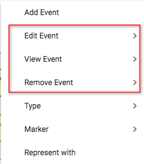
To add a boundary event, right click a task and select Add Event
Select an existing event or create a new event in the Event field. Select
The position you wish it to appear on the task
The Flow of the event
The Trigger on the event
If it is interrupting or not - checking the box makes it non-interrupting
Press OK once you are done.
The boundary event can then be seen on the task
You can edit, view the details or remove the boundary event, by right clicking a task and selecting one of the option from the context menu.

Gateway Objects
|
Name |
Options |
Image |
Description |
|
Gateway |
|
|
|
|
|
Exclusive |
|
A diverging Exclusive Gateway is used to create alternative paths within a Process flow. This is basically the “diversion point in the road” for a Process. For a given instance of the Process, only one of the paths can be taken. |
|
|
Inclusive |
|
Used to create alternative but also parallel paths within a Process flow. Unlike the Exclusive Gateway, all condition Expressions are evaluated. The evaluation of one condition does not exclude the evaluation of other conditions. Since each path is considered to be independent, all combinations of the paths MAY be taken, from zero to all. However, it should be designed so that at least one path is taken. |
|
|
Parallel |
|
A Parallel Gateway is used to combine parallel flows and to create parallel flows. Not evaluating any condition or event, but used to represent two concurrent tasks in a business flow. |
|
|
Complex |
|
Used for the most complex flows in the business process, often when you need multiple gateways to describe the business flow. |
|
|
Event-Based |
|
Similar to an exclusive gateway, the event-based gateway involves one path in the flow. The alternative paths that follow the gateway are based on the events that occur, rather than data seen in the process. |
|
|
None |
|
A Gateway is used to control the convergence and divergence of Sequence Flows in a Process. It determines the possible branching, merging, forking and joining of paths. Markers on the gateway will indicate the type of behavior control. The term “Gateway” implies that there is a gating mechanism that either allows or disallows passage through the Gateway. |
|
|
Parallel Event-based |
|
This gateway is similar to a parallel gateway, allowing multiple processes to happen at the same time. Unlike the parallel gateway, the processes are not dependent on events, multiple events can trigger multiple processes. |
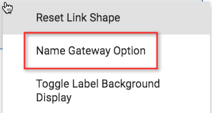
You can add labels to the gateway lines, by right clicking the line and seleting to Name Gateway Option

Task Objects and Sub processes
|
Name |
Options |
Image |
Description |
|
Task |
Type |
|
|
|
|
None |
|
A Task is an atomic Activity within a Process flow. A Task is used when the work in the Process cannot be broken down to a finer level of detail. Generally, an end-user and/or applications are used to perform the Task when it is executed. |
|
|
Receive |
|
A Receive Task is a simple Task that is designed to wait for a Message to arrive from an external Participant (relative to the Process). Once the Message has been received, the Task is completed. |
|
|
Script |
|
A Script Task is executed by a business process engine. The modeler or implementer defines a script in a language that the engine can interpret. |
|
|
Manual |
|
A Manual Task is a Task that is expected to be performed without the aid of any business process execution engine or any application. An example of this could be a telephone technician installing a telephone at a customer location. |
|
|
Service |
|
A Service Task is a Task that uses some sort of service, which could be a Web service or an automated application. |
|
|
User |
|
A User Task is a typical “workflow” Task where a human performer performs the Task with the assistance of a software application and is scheduled through a task list manager of some sort. |
|
|
Send |
|
A Send Task is a simple Task that is designed to send a Message to an external Participant (relative to the Process). Once the Message has been sent, the Task is completed. |
|
|
Business Rule |
|
A Business Rule Task provides a mechanism for the Process to provide input to a Business Rules Engine and to get the output of calculations that the Business Rules Engine might provide. |
|
Sub-process |
Markers |
|
|
|
|
Compensation |
|
Compensation is a specialized version of a task object that only happens when another specific task occurs previously to it. |
|
|
Multiple intances |
|
Allows for creation of a desired number of task instances. The instances MAY execute in parallel or MAY be sequential. |
|
|
Loop |
|
Tasks MAY be repeated sequentially, essentially behaving like a loop. e.g. 'edit draft'. |
|
|
Ad-Hoc |
|
An ad-hoc task is one which has no sequence: the order in which their constituent tasks are performed is unknown or unspecified. |
Set Task Type
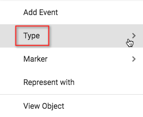
Right click a task and select Type from the context menu. You can then select the type.

Set Task Marker
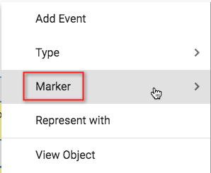
Right click a task and select Marker from the context menu. You can then select the marker(s) to be applied.

Sub-process
BPMN provides us with the sub-process. This can be shown using either the expanding/collapsing view of a task, or by creating a URL attribute in the task object and using the URL of the child diagram that explains the process in more detail.
Sub-Process (Collapsed) - The details of the Sub-Process are not visible in the Diagram. A “plus” sign in the lower-center of the shape indicates that the Activity is a Sub-Process and has a lowerlevel of detail.
Sub-Process (Expanded) - The boundary of the Sub-Process is expanded and the details (a Process) are visible within its boundary. Note that Sequence Flows should cross the boundary of a Sub-Process.
Events, tasks and gateways can be dragged into tasks to create a sub-process. Once saved, the objects in the sub-process will have a new 'contained in' relationship added to them and the sub-process will have a 'contains' relationship to the objects that describe it in more detail.
Connecting Objects
|
Name |
Images |
Description |
|
Sequence |
|
A Sequence Flow is used to show the order that Activities will be performed in a Process. |
|
Message |
|
A Message Flow is used to show the flow of Messages between two Participants that are prepared to send and receive them. |
|
Data Association |
|
An Association is used to link information and Artifacts with BPMN graphical elements.
|
Creating relationships between objects on the BPMN diagram
To create a relationship between objects, select the source object, click the link adornment button and drag toward the target object for the relationship (a pink box will appear around the target).
Once the relationship has been accepted, a dialog box will pop up asking you to select the type of relationship you would like to use.
Create Relationships by dragging and dropping
Within the BPMN diagram, dragging and dropping an object onto another object, e.g. an event into a lane, will create a 'contained in' relationship in the model.
The object cannot then be removed, until you have right clicked and select 'Remove from group', which will remove the relationship from the model.
This also extends to a sub-tasks representation.
Swimlane objects
|
Name |
Images |
Description |
|
Pool |
|
A Pool is the graphical representation of a Participant in a Collaboration. It also acts as a “swimlane” and a graphical container for partitioning a set of Activities from other Pools. A Pool MAY have internal details, in the form of the Process that will be executed. Or a Pool MAY have no internal details, i.e., it can be a "black box." |
|
Lane |
Populated within Pools |
A Lane is a sub-partition within a Pool and will extend the entire length of the Pool, either vertically or horizontally. Lanes are used to organize and categorize Activities.
|
How to draw Pools/Lanes
To add a pool, click and drag a Pool object from the pallete onto the diagram.
If you add a new pool, a dialog will appear, where you can
Name the pool, creating a new pool, or re-use an existing pool by using the drop down list
Select an ArchiMate model object that this pool represents in this process flow (explained further later in this section)
Add Lanes to the pool, either new or existing
|
|
If you re-use an existing pool, the lanes that also exist and have a relationship to that pool will be pre-populated into the lanes section. You can either choose to use these or remove them using the 'x' in their row. |
The Pool to Lane relationship can be viewed in the relationships tab from either object.
To Add or Remove Lanes from a pool on the diagram
Right click the pool and choose Configure Pool.
The dialog will open that will allow you to add or remove lanes from the pool.
Artifacts
|
Name |
Images |
Description |
|
Data Object |
|
Data Objects provide information about what Activities require to be performed and/or what they produce, Data Objects can represent a singular object or a collection of objects. |
|
Data Store |
|
A DataStore provides a mechanism for Activities to retrieve or update stored information that will persist beyond the scope of the Process. The same DataStore can be visualized, through a Data Store Reference, in one or more places in the Process. |
Layouts
There are several layouts supported for use with BPMN - these can be found under the View > Layout menu;
Standard - This allows a user to layout the diagram as they wish and show connections from top, bottom, left and right of all objects
Parallel - This limits the connections from tasks, events and gateways to be from right or left of the objects
Auto Parallel - This is a mode that will lay out the diagram for users. Whilst the checkbox is checked, any object added to the diagram will be added in the most logical place - it will move accordingly as connections are made to it and from it. You will need to move into Standard or Parallel options to be able to move the shapes to where you want them.
The diagram and swim lanes can be modelled in horizontal or vertical fashion.
You may want to change the routing of a relationship that has been drawn in Auto Parallel mode, once you come out of that mode. To do this right click the relationship, and select Reset Link Shape option - this will make the link direct again.
Represent ArchiMate objects with the BPMN process flows
We still want to use the BPMN process flows created by our team in the context of our enterprise architecture. To do this, we can choose to allow the BPMN objects created to 'represent' existing objects from our model - this gives us context as to the wider effects that a process change might have and ensures we don't work in a silo, just because this process is the only thing in our remit.
When we add a Pool object to a BPMN diagram, we will be offered the 'Representing object' field, within the configuration dialog. For other objects, the 'Represent with' option can be found in the right click context menu.
Once an object is selected, it will be displayed in brackets in the name of the BPMN objects on the diagram. The example below, the BPMN process 'Check Credit' is now representing an ArchiMate business process 'Credit check'. A common use for this will be to represent BPMN Lane objects as business roles/actors that exist within the model.
A 'represented by/represents' relationship can be seen for this within the Relationships tab of both objects.
Diagram Kinds
Using a diagram kind, you can create a diagram type that uses the traits of another diagram type, but you can control the object types associated with it.
In this context, if we created a new diagram type, of 'kind' BPMN, we can tailor what model object types can be represented by BPMN Objects. As default any existing model object can be selected to be represented.
To do this, go to User menu > System > Diagram Types
Add a new diagram type (using the + button)
Name the type
Select the kind to be BPMN
In the Represented By field, select the existing model object types you would like to allow to be selected. You may create different versions for different teams, to control the objects they can select within the model.
- As you have selected the BPMN kind, the Object Types option will be greyed out.
Once this is done, you can begin creating your new custom BPMN diagrams.
Example BPMN process flow
Login
Role Applicable to: Client Administrator, User, Contributor, Reviewer
You can login with your user name and password.
If you have forgotten either of these, you can click on the button at the end of each field to recieve the information via email.
|
|
If you want to add an icon for the platform to your desktop, drag and drop the icon next to the URL to your home screen. On an iPad or Android, follow the local instructions for your browser. |