|
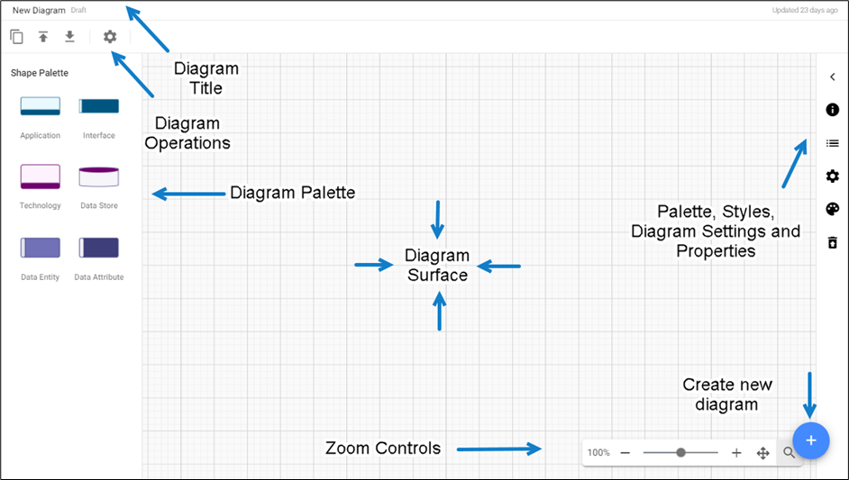
Formatting Shapes in Diagrammer
Adding Shapes, Connecting Lines to the Diagram, and Changing Properties
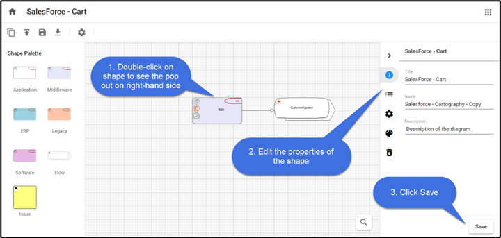
To add shapes to the diagram,
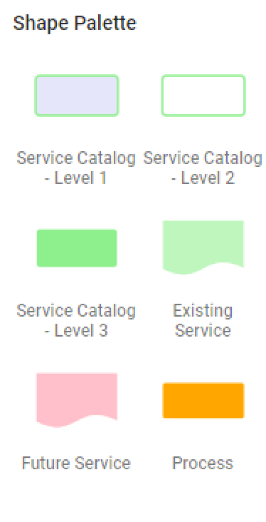
1.Drag and drop the required shape from the Shape Palette.
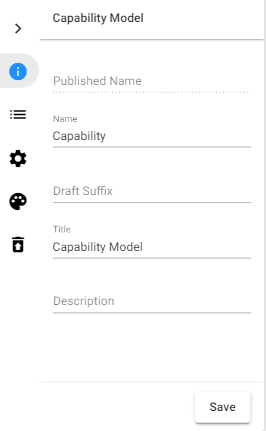
2.Double-click on the object shape to edit the Title and its Properties.
3.Click Save.
You can use a Connector to link two Shapes, indicating that there is a connection between the two shapes.
To add the connector between the shapes,
1.Select the first shape by clicking on it.
2.Click on one of the + symbols to add the connector and move your mouse pointer to the shape you would like to connect to.
3.Click on the shape to end the selection.
4.If there are multiple connection types between these kinds of objects, you will get a menu to choose the connection that is appropriate.
To Clear or Delete Shapes from the Diagram
Object Shapes can be Cleared or Deleted from the diagram in two ways.
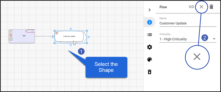
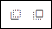
To Clear a Shape:
When you choose to Clear a shape, it removes the shape from the diagram, but it does not remove the object it represents from the model.
1. Select the shape you wish to Clear.
2. Click on  icon. icon.
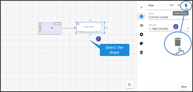
To Delete a Shape:
When you choose to Delete a shape, it removes the shape from the diagram, and when published will remove the object representing from the model too.
1.Select the shape you wish to Delete.
2.Click on  icon. icon.
|

|
If a shape is deleted, any connector associated with the object shape also gets deleted. |
|
|
When object shapes are deleted using the Delete option, it adds the item to the Trash can icon called Deleted Objects on the right-hand pane. |
Adding Background Colors and Borders to the Shapes
Every Shape from the Palette has a definite background color, border size, and border color.
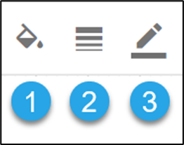
You can format the shape by
1.Background Color of the shape.
2.Border Size to the shape.
3.Border color to the shape.
|
|
When object shapes are deleted using the Delete option, it adds the item to the Trash can icon Some shapes may have Region shapes and Region formatting which overrides these styles such that the style options will not work.
Example: A shape may be set with color because of the “Category” of the object, i.e. the shape may be Red because it is a critical object (as defined in one of its properties). |
Aligning Shapes
Object shapes in the editor can be aligned using Align Nodes placed on the toolbar.

Object shapes can be aligned to the Left, Right, and Center horizontally, and also Top, Bottom, and Center vertically, which can also be evenly Distributed Horizontally or Vertically.

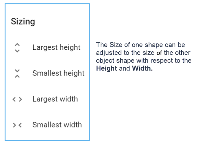
Resizing Shapes to match others
In the Diagrammer, the object shape can be adjusted to the height and width of the other shape using Resize Nodes.

Move Shapes from Back and Front
In the diagram, if one shape is put on top of another, it may conceal the other.
Move To Back and Move To Front buttons help to show/Hide the object shape.
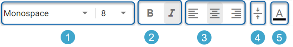
Text Formatting and Fonts
The Title of Object shapes can be formatted according to:
1.Font and its Font Size
2.Text in Bold, and Italic
3.Text alignment to Left, Center, and Right.
4.Vertical Alignment.
5.Text Color.
|
|
Some shapes may have Region shapes and Region formatting which overrides these styles such that the style options will not work.
Example: A shape may use a different property for the Title, that is defined in a region. This region’s style cannot be overridden by Diagrammer |
|