You can associate any object with another object that is not part of the diagram. Additionally, you can view, add, update and delete multiple associated objects and their properties in erwin Web Modeler by configuring Evolve Designer.
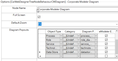
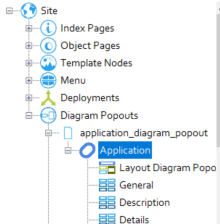
To view the list of Object Types displayed in the Diagram Popouts:
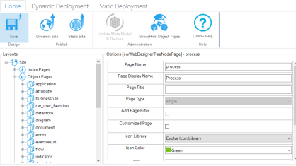
1.Start Evolve Designer.
2.Click a model. For example, EA Foundation – Sample Model.
3.Click Site.
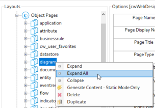
4.Expand Site > Object Pages.
5.Right-click diagram and click Expand All.
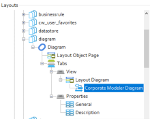
6.Click Corporate Modeler Diagram.
The list of Object Types appears under Diagram Popouts.
To create an Object Type Association:
1.Start Evolve Designer.
2.Click a model. For example, EA Foundation – Sample Model.
3.Click Site.
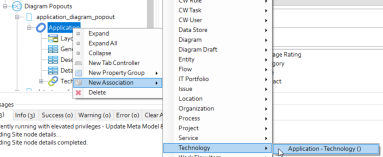
4.Expand Site > Diagram Popouts > application_diagram popout > Application.
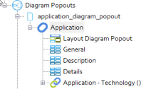
5.Right-click Application and click New Association > Technology > Application – Technology ().
|
|
You can add any Object Type Associations. |
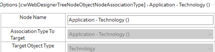
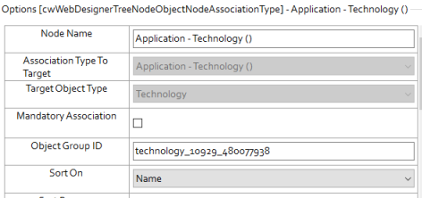
6.Click Application – Technology () node.
7.In the Node Name box, replace “Application – Technology ()” with “Technologies”.
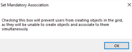
8.Optional: If you want the diagram user to be forced to have at least one associate object, then select the Mandatory Association check box.
A Set Mandatory Association pop-up appears.
9.Click OK.
10.Click Save.
11.Click Dynamic Site.
The Associated Objects are now visible in the diagram.
To view the Associated Objects in the diagram:
1.Open the browser and login to erwin Evolve Web.
2.Click a model. For example, EA Foundation – Sample Model.
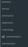
3.In the left pane, click Application.
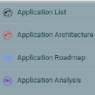
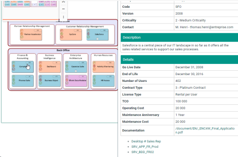
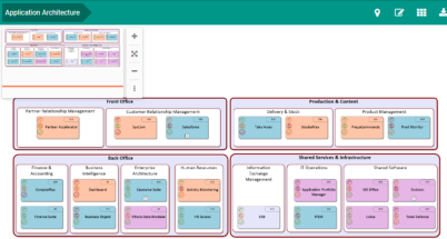
4.Click Application Architecture.
5.Click the required object for which you want to view Associated Object. For example, Salesforce.
The Associated Objects Types are now visible in the right pane.
To add Associated Objects in erwin Web Modeler:
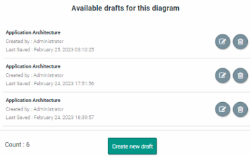
1.Click the Edit Diagram In Web Modeler icon.
2.Click Create new draft.
The erwin Web Modeler editor opens in the new tab with the predefined Shape Palette of the selected template.
3.Select the object for which you want to add Associated Object. For example, Salesforce.
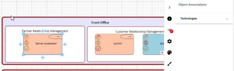
4.Click 
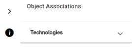
The Object Associations list appears.
5.Click the Technologies drop-down list.
6.Click Add Associated Object.
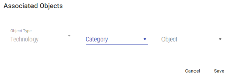
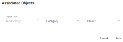
Associated Objects pop-up opens.
|
|
The Object Type field is pre-populated with the Object Type to which you want to add an Associated Object. |
7.Click the Category drop-down list and select the required option.
8.Click the Object drop-down list and select the required option.
9.Click Save.
10.Click 
11.Click Confirm Publish.
Once the diagram is published in the erwin Web Modeler, you can access it from the Modeler in the erwin Evolve Suite.
Mandatory Association
Mandatory Association enforces you to add at least one Object Association.
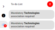
If no Associated Object is added, a pending task appears in the To-do List and the Publish Diagram is disabled.
To add Mandatory Association:
1.Click 
To-do List opens.
2.Click the pending task. For example, “Mandatory Technologies association required”.
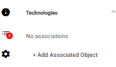
Once pending task selected, the object is selected automatically, and the Object Association section appears in the right pane.
3.Click the Technologies drop-down list.
4.Click Add Associated Object.
The Associated Objects pop-up opens.
|
|
The Object Type field is pre-populated with the Object Type to which you want to add an Associated Object. |
5.Click the Category drop-down list and select the required option.
6.Click the Object drop-down list and select the required option.
7.Click Save.
8.Click
9.Click Confirm Publish.
Once the diagram is published in the erwin Web Modeler, it can be accessed from the Modeler in the erwin Evolve Suite.
|
|
Please check with your Administrator that firstly, your Server and Internet Browser meet the necessary system requirements to use Web modeler. Secondly, check with your Administrator that the Web Modeler feature is enabled. |
This page explains how to format shapes in the Web Modeler online step by step.
Adding Shapes, Connecting Lines To The Diagram, and Changing Properties
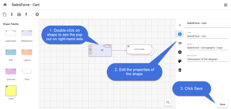
To add shapes to the diagram,
1.Drag and drop the required shape from the Shape Palette.
2.Double-click on the object shape to edit the Title and its Properties.
3.Click Save.
You can use a Connector to link two Shapes, indicating that there is a connection between the two shapes.
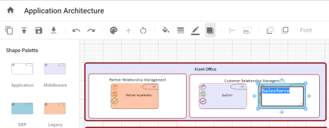
In-Place editing in the shape,
You can edit the name of a shape in the diagram editor using In-place editing.
To edit the name of the shape,
1.Select the shape you wish to edit.
2.Click again on the shape and then enter the text.
3.Either press Enter or click anywhere on the editor to finish editing.
To add the connector between the shapes,
1.Select the first shape by clicking on it.
2.Click on one of the + symbols to add the connector and move your mouse pointer to the shape you would like to connect to.
3.Click on the shape to end the selection.
4.If there are multiple connection types between these kinds of objects, you will get a menu to choose the connection that is appropriate.
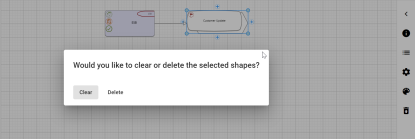
To Clear or Delete Shapes from the Diagram
Object Shapes can be Cleared or Deleted from the diagram in two ways.
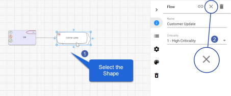
To Clear a Shape:
When you choose to Clear a shape, it removes the shape from the diagram, but it does not remove the object it represents from the model.
1. Select the shape you wish to Clear.
2. Click on 
Or
1.Select the shape you wish to Clear.
2.Press the Delete button on your computer's keyboard.
3.Confirm to Clear.
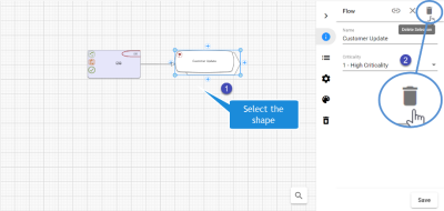
To Delete a Shape:
When you choose to Delete a shape, it removes the shape from the diagram, and when published will remove the object representing from the model too.
1.Select the shape you wish to Delete.
2.Click on 
Or
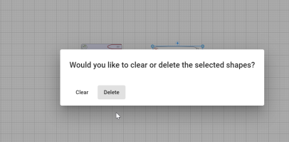
1.Select the shape you wish to Delete.
2.Press the Delete button on your computer's keyboard.
3.Confirm to Delete.
|
|
If a shape is deleted, any connector associated with the object shape also gets deleted. |
|
|
When object shapes are deleted using the Delete option, it adds the item to the Trash can icon called Deleted Objects on the right-hand pane. |
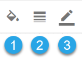
Adding Background Colors and Borders to the Shapes
Every Shape from the Palette has a definite background color, border size, and border color.
You can format the shape by
1.Background Color of the shape.
2.Border Size to the shape.
3.Border color to the shape.
|
|
Some shapes may have Region shapes and Region formatting which overrides these styles such that the style options will not work. |
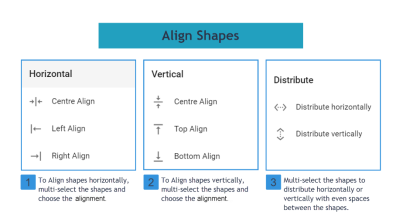
Aligning Shapes
Object shapes in the Web Modeler editor can be aligned using Align Nodes placed on the toolbar.
Object shapes can be aligned to the Left, Right, and Center horizontally, and also Top, Bottom, and Center vertically, which can also be evenly Distributed Horizontally or Vertically.
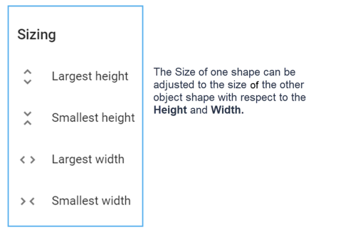
Resizing Shapes to match others
In the Web Modeler Editor, the object shape can be adjusted to the height and width of the other shape using Resize Nodes.
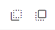
Move Shapes from Back and Front
In the diagram, if one shape is put on top of another, it may conceal the other.
Move To Back and Move To Front buttons help to show/Hide the object shape.
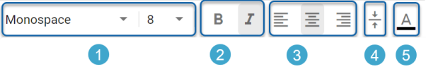
Text Formatting and Fonts
The Title of Object shapes can be formatted according to:
1.Font and its Font Size
2.Text in Bold, and Italic
3.Text alignment to Left, Center, and Right.
4.Vertical Alignment.
5.Text Color.
|
|
Some shapes may have Region shapes and Region formatting which overrides these styles such that the style options will not work. |
In the Diagrammer, you can upload pictures to the shape palette of the diagram and publish them.
To upload the pictures:
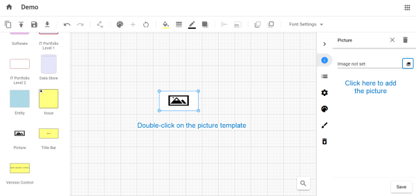
1.Go to the diagram template or the existing diagram to which you wish to add pictures.
2.From the shape palette, drag and drop the picture template. Double-click on it to view the properties pane on the right side.
3.Click on the 
|
|
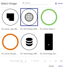
Gallery Manager displays all pictures available in the model with the most recent pictures at the top. |
4.To upload a picture, click on Upload at the top-right corner.
5.Select an image and click on Select.
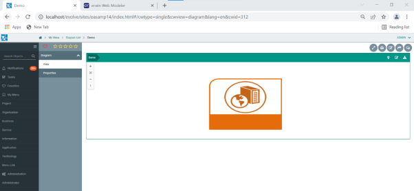
The picture appears on the draft diagram.
6.Once the draft is ready, click Publish Diagram icon.
7.After publishing the draft, picture can be viewed in erwin Evolve Web or erwin Evolve Suite.
Options that are generally available for any diagram in the canvas are:
1.Duplicate Draft
2.Publish Diagram
3.Save Diagram
4.Download Diagram
5.Undo and Redo
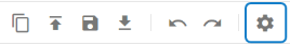
6.Diagram Settings
Duplicate Draft
To duplicate the working draft of the diagram, click on Duplicate Draft on the toolbar.
By doing this, a copy of the draft will be created, and you will be taken immediately to the draft diagram. It will also be available in the Web Modeler Home.
The draft diagram will be associated with the originally published diagram, and on publishing will replace the same published diagram.
|
|
To create a separate published diagram, you should duplicate the published diagram instead. |
Publish Diagram
To publish the diagram, click on Publish Diagram icon on the toolbar.
Before proceeding to Publish the diagram, make sure you don’t have any incomplete items in To-Do list. Once published, the draft diagram will be deleted, and the published diagram will be available on the Evolve site and in Modeler.
Save Diagram
To save the diagram, click on Save Diagram on the toolbar.
Although drafts are continuously saved to a secondary storage, saving your draft diagram ensures it is kept in your Evolve database and can be backed up with your main database backup.
Download Diagram
To download the diagram in the form of an image to your machine, click on Download Diagram on the toolbar.
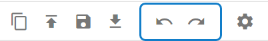
Undo and Redo
You can Undo or Redo the changes made in the diagram editor.
To apply click on Undo/Redo options on the toolbar.
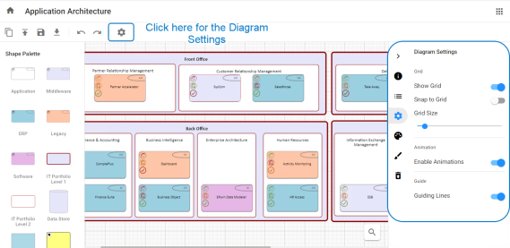
Diagram Settings
To apply the settings related to the diagram Grid, Animation and Guiding lines in the editor, click on Diagram Settings on the toolbar.
You will see a panel popped up on the right-side of the screen to work on settings.