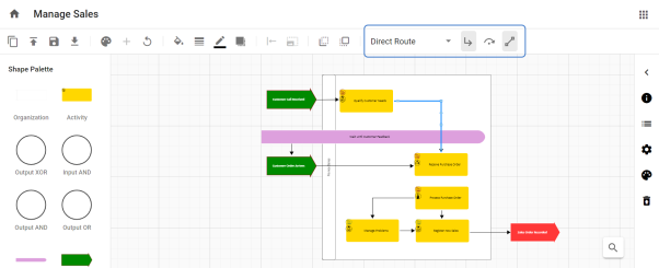
The lines which associate the two objects in the diagram are called Connector Lines.
On Selecting the line, options for connector lines are shown on the toolbar.
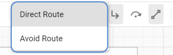
Lines can be applied in two ways:
1.Direct Route – connects the objects using the shortest path.
2.Avoid Route – connects the objects avoiding the other objects in the diagram structure.
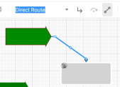
Lines are of three types are available to connect the objects:
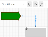
1.Orthogonal Lines – Orthogonal Lines are when the line appears with right angles in order to connect the two objects when it cannot be drawn horizontally or vertically.
This line is available only under Direct Route and will be disabled for Avoid Route.
|
Orthogonal Off |
Orthogonal On |
|
|
|
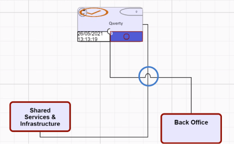
2.Jump Lines – Jump Lines are when one connecting line passes over another, and it appears with an arc over it.
This button are used in conjunction with the orthogonal lines button. If an orthogonal line is off for a particular line then the jump line button is disabled.
Jump is a property of an individual line, so if the lines cross and neither have the jump property then they look like straight lines passing through one another. Jump lines will be seen if both lines have jump property.
3.Lock/Unlock Link Port – Link Ports can be Locked or Unlocked. To lock them, either press the button or move the connection point (port) of the line, around the shape. When you select a location to port the line to the shape, it will become locked. If you want the diagrammer to automatically reposition the port, select the line, and press the unlock button, to release the lock.
Locking the link ports helps to keep the specific connection point when the shapes are moved around the canvas.
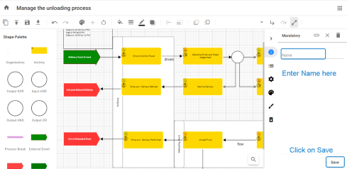
Naming on Association Links
To show the flow between the shapes, Association Names can be placed on Association Links.
To place the name on the link,
1.Double-click on Link or Connector Line you wish to add on.
2.A property panel will be opened on the right-side of the screen.
3.Enter Name and then click on Save on the bottom of the screen.
4.The Association Name can be moved around the screen by Clicking and Dragging it to a new location.
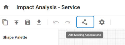
How to Add Missing Associations?
Associations between the shapes can be automatically displayed if a new object is added to the existing diagram. This will render the associations between the existing objects and the newly added objects in the existing diagram.
You can also place associations between any two or multiple objects using the button on the toolbar called Add Missing Associations.
Associations can be applied in three ways:
•Upon Single Selection – Select any single object shape in the diagram and then click on Add Missing Association button to display the associations related to the selected object shape and the other shapes in the diagram.
•Upon Multi Selection – Selection of any two or more shapes will render the missing associations to the objects that are already defined between them
•No Selection – This will render all possible associations between the shapes in the diagram.
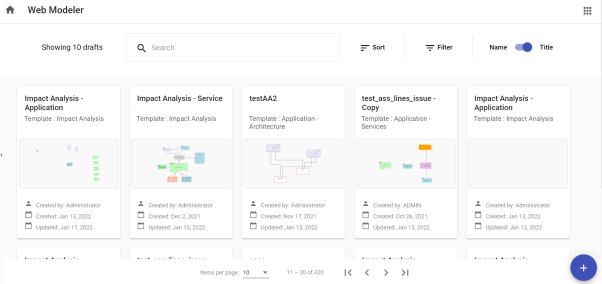
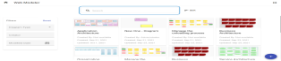
Web Modeler Home page also known as Draft Manager [from version 2020.2.0] allows more control over your drafts. Providing significant features such as Search, Sort and Filters.
A new diagram can be created by choosing from the available templates in Web Modeler.
•Search – You can search for existing diagrams with the keywords in the Search Box.
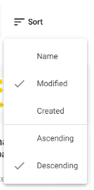
•Sort – You can Sort the diagram drafts with several available options.
oName or Title of the diagram
oWho it was last Modified by
oWho originally Created the draft
oSort the list by Ascending and Descending order
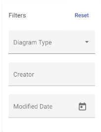
•Filters – Diagrams in the draft manager can be filtered by,
oDiagram Type
oCreator of the diagram
oModified Date – ‘From Date’ to ‘To Date’
To reset the applied filters, click on Reset.
•Toggle between Name and Title – List of diagrams will be displayed as per the toggle selection. You can choose to display the diagrams as per the Name or Title of the diagram.
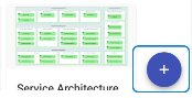
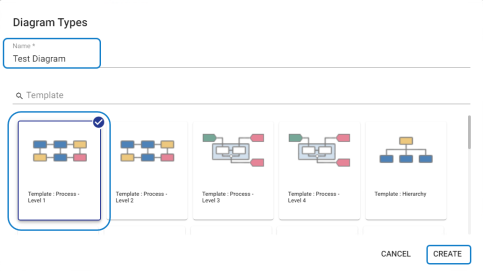
•Create New Diagram – A new diagram can be created from the scratch by using the existing template.
oClick on + symbol from the bottom right of the screen.
oEnter Name of the new diagram > Select Template > click on Create.
The instructions on this page detail how to set a Parent object and object name in erwin Evolve Suite (CW Suite), erwin Evolve Web, and erwin Web Modeler.
To set the Parent object and object name in erwin Evolve Suite:
1.Start the erwin Evolve Suite.
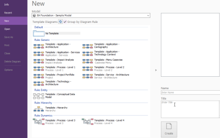
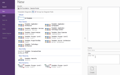
2.Click Modeler.
3.Select the Model and Template that you want use to create a diagram.
4.Enter the name of the diagram in the Name box and then, click Create.
5.Drag and drop the required shapes from the palette onto the diagram surface.
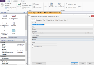
6.Double click on the diagram surface or under the Home tab, click Properties.
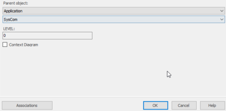
The Diagram properties dialog box appears.
7.Click the first drop-down list box under Parent object and select the required parent object.
8.Click the second drop-down list box under Parent object and select the required parent object name.
9.Click OK.
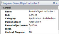
10.Click on the Refresh icon.
You can see the same Parent object and Parent object name on the left pane.
|
|
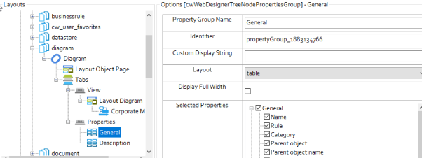
Before setting the Parent object and Parent object name in erwin Evolve Web, first, we need to enable these options (Parent object and Parent object name) in Evolve Designer and publish them on the site. |
To enable Parent object and Parent object name in Evolve Designer [Evolve 2022.0.0 and above]:
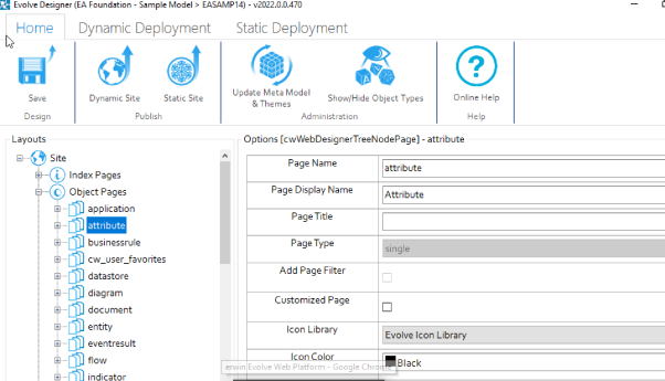
1.Start Evolve Designer.
2.Click on a model. For example: A Foundation – Sample Model.
3.Click Site.
4.Expand Site > Object Pages.
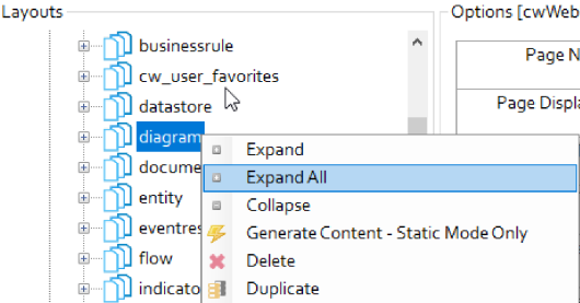
5.Right-click on diagram and click Expand All.
6.Click General and under Selected Properties, select Parent object and Parent object name.
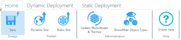
7.Click Save and then, click Dynamic Site to generate the site.
To set the Parent object and Parent object name in erwin Evolve Web:
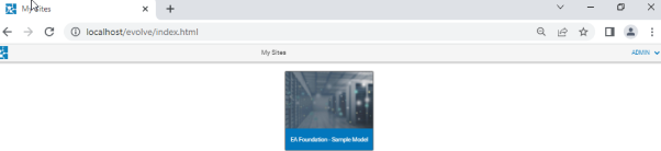
1.Open the browser and login to erwin Evolve Web.
2.Click on model. For example: A Foundation – Sample Model.
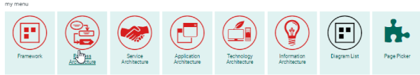
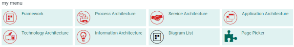
3.Under my menu, click Diagram List.
The Diagram List appears.
4.Enter the diagram name in the Filter the content of this page box.
5.Click on the 
The diagram opens on your object page.
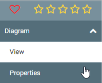
6.In the Diagram drop-down list, click Properties.
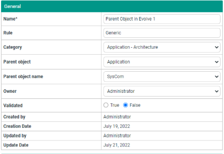
7.Click the Edit icon to edit the Parent object and Parent object name.
8.Click the Parent object drop-down list and select the required option.
9.Click the Parent object name drop-down list and select the required option.
10.Click the Save changes icon.
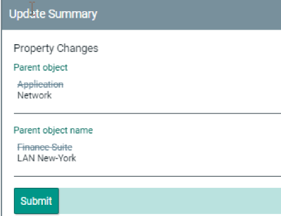
The Update Summary details appear on right pane.
11.Click Submit.
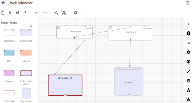
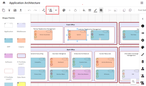
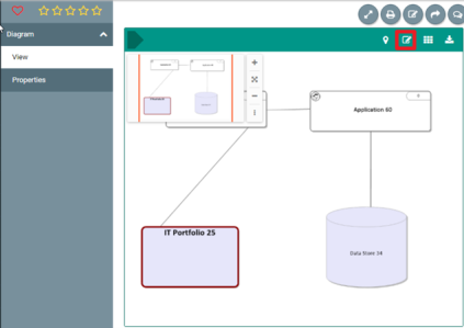
To set Parent object and Parent object name in erwin Web Modeler:
1.Click View.
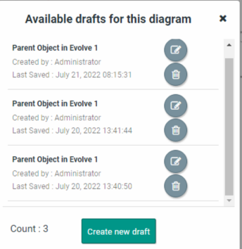
2.Click the Edit Diagram In Web Modeler icon.
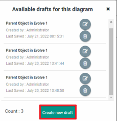
3.Click Create new draft.
The erwin Web Modeler editor opens in a new tab with the predefined Shape Palette of the template chosen.
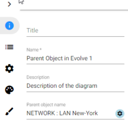
4.Click on the 
5.Click on the 
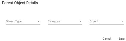
Parent Object Details popup opens.
6.Click the Object Type drop-down list and select the required option.
7.Click the Category drop-down list and select the required option.
8.Click the Object drop-down list and select the required option.
9.Click Save.
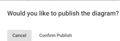
To publish the diagram:
1.Click the Publish Diagram icon.
2.Click Confirm Publish.
Once the diagram is published in the erwin Web Modeler, it can be accessed from the Modeler in the erwin Evolve Suite.
|
|
Diagram and Palette properties can be modified, if required, from the desktop application. |
To link parent objects to existing child draft diagrams:
1.Open the browser and login to erwin Evolve Web.
The list of available models appears.
2.Click a model. For example, EA Foundation – Sample Model.
3.Under my menu, click Diagram List.
The list of diagrams opens.
4.Enter the diagram name in the Filter the content of this page box.

6.Click the Open related object page 
The diagram opens on your object page.
7.Click the Edit Diagram In Web Modeler icon.
|
|
In the absence of the Edit Diagram In Web Modeler option, ensure that the Web Modeler is enabled with a Diagrammer license for you. |
8.Click Create new draft.
Evolve Web Modeler editor opens in a new tab with the predefined Shape Palette of the chosen template.
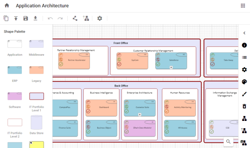
9.Select an object.
Options are now enabled.
10.Click the drop-down arrow on the Explode New Draft 
The Link Draft Diagrams option appears.
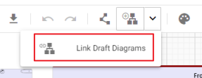
11.Click Link Draft Diagrams.
The Add Link to Existing Draft appears.
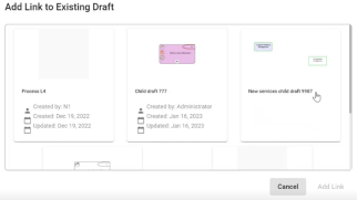
12.Select any child draft diagram to link with an object.
13.Click Add Link.
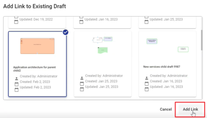
The child draft diagram is now linked to a parent object.
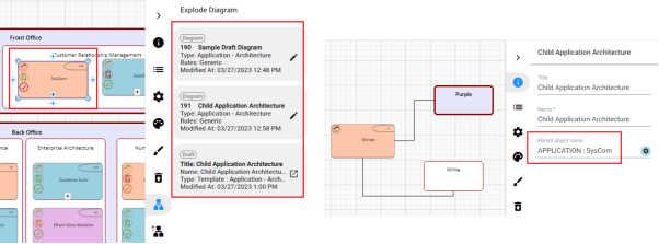
You can now see that parent object has draft child diagram available in the properties. Also, the name of the parent object is included in the child draft diagram.