Once your model is activated you are ready to add diagram layouts.
On first use, you will not have any diagram layouts created, so you need to create your first diagram layout.
To create a diagram layout, click on the “Add a Layout Icon” 
|
Option |
Description |
|
Layout Name |
The name of your automatic diagram template (diagram layout). This name will help you to find your template layout |
|
Diagram Template |
The erwin EA/BP Desktop Modeler template which is used by the Diagram Designer to generate a diagram. The elements in the Palette of the diagram template are used for the default size of the shapes. If the Object Type is not in the template palette, you will not be able to choose it in the creation of your diagram layout. |
|
Output type |
There are 2 options for the output type of your diagram : Group one or more objects on a diagram This option allows you to put all the selected primary objects on the same diagram. This option is used for heat map or big pictures diagrams. Generate on diagram for each base object This option allows you to create one diagram for each base object you will choose later. This option is used for spider or flow diagrams. |
Related Items
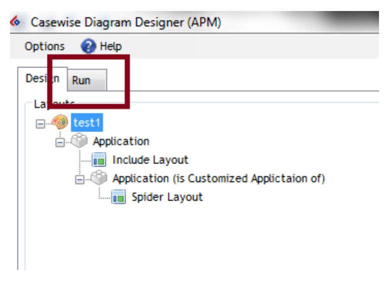
To configure your diagram layout, you need to be in the design mode, changing the mode is possible using the Tabs below the options toolbar.
The design of your diagram layout is decomposed on the following steps:
1. Creation of the diagram layout
2. Definition of the object type(s) to select (Node)
3. Definition of output layout(s) to apply to the selected objects (Display)
4. Repeat step 2 as needed
That is, each time you choose a node (Set of Object Types) and a layout (Display), you can then if required, add a sub level node using an Association Type.
In Diagram designer the selection of data is done using a graph structure. You will need to select the Object Type(s) from which you want to start and then select Association Types from this object. A selection of objects is called a “node”. For each node of objects you have to define which layout will be used to display them in the diagram.
Three main layouts are available to apply to a Node :
1. Include layout : Have objects contained within a diagram or other object
2. Vertical layout : Have objects displayed to the right or left of the parent object
3. Spider layout : Have objects placed around the parent object
From each Node it is then possible to repeat the process of decomposing to sub nodes through associations, to sub nodes.
Related Items
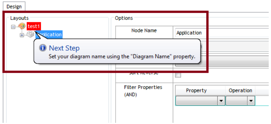
The Diagram Designer is designed to help you and propose you the next step depending on where you are in the configuration of your automatic diagram template.
Each time a node has a red background, the meaning is that something is wrong or an action is required. The Next step text is here to guide and help you. To see the message you need to hover with your mouse over the element which has a red background.
|
Icon |
Node Name |
|
|
Design Layout, contain the design options |
|
|
Object Node, either Object Type or Association Type |
|
|
Node Layout, used to define the display type of the objects in the diagram |
Design Mode
Once your configuration layout has been created you will be able to select objects and define a diagramming layout.
Depending on the output type you have choose the diagram layout options vary.
Group Mode Output Type Options
|
Option |
Description |
|
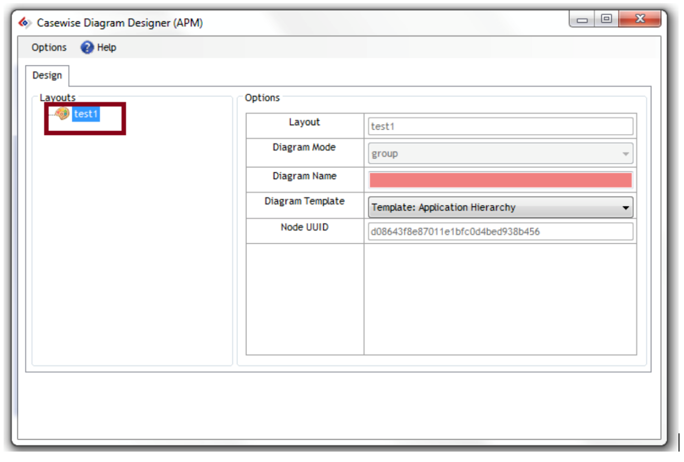
Diagram Name |
As you have choose the group mode, you will need to define the name of your diagram, as you will choose one or several objects to display on the diagram, the Diagram Designer can’t define the name. |
Single Mode Output Type Options
The name of your diagram in the single mode will be the concatenation of the defined prefix + the name of the primary object + the defined suffix.
|
Option |
Description |
|
Diagram Name Prefix |
This text will be used to prefix the name of the primary object to create the name of the diagram. This option should be customized in order to avoid collision with existing diagram. Please include a space character after the prefix if you want a space between the prefix and the name of the primary object. |
|
Diagram Name Suffix |
The suffix will be used for the name of the diagram. It will be set just after the name of the primary object. |
To define the options for your diagram layout, left click on the root node and you will have the options at the right side of the screen.
Add Objects to the Diagram
Primary Object:
To add a primary object group you need to right click on the diagram layout node and choose the Object Type you want to use.
|
|
Notice that only Object Types on the palette entry of your diagram template are displayed. Notice also when you create the primary object node you have an include type layout which is automatically added as a children of your object type node. This is because the first layout should always be an Include Layout. |
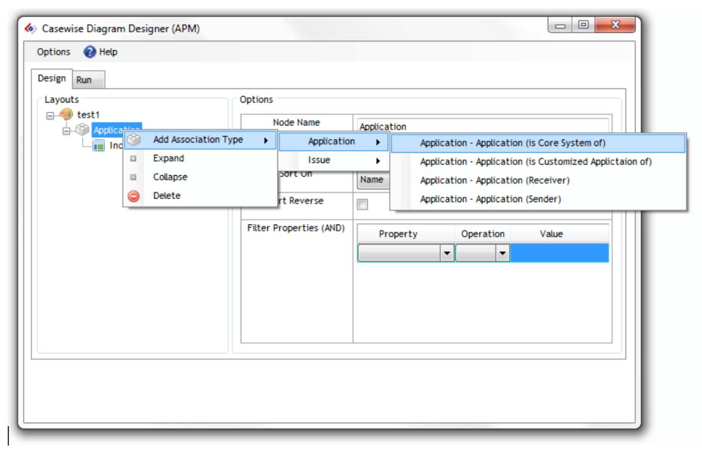
Association Types:
To continue adding objects, you need to right click on the parent node where you want to add an Association Type, Objects Type associated to the selected Object Type are proposed in the context menu.
|
|
Notice that the Target Object Types should be present on the palette entry in order to have them in the contextual menu. |
Then from any association type node you can do the same operation.
|
|
Notice that when you create an Association Type node, you will have to add the associated design layout. Please refer to the "Add a Design Layout" section. |
Object Node Options
The Object Selections node is used to specify the rules that determine which instances should be displayed at the level you are working.
Here are the available options :
|
Option |
Description |
|
Sort on |
Which property to sort the results by |
|
Sort Reverse |
Sort in reverse order |
|
Filter Properties |
Use this section to choose some rules for specifying exactly which objects you want returned – “where Category = A” etc� |
|
|
Notice that filters are using the “AND” operator when several filters are available. |
Design Types
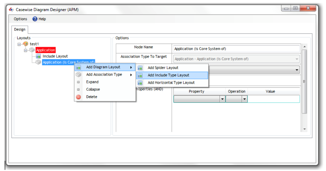
Add a design layout
To add a Design Layout, you need to right click on an object node without any Design Layout. On the context menu you will have the option “Add Diagram Layout”, and then choose the diagram Layout you want to use depending on your requirements.
|
|
Notice if your node has already a design layout attached, and you want to change it, you need first to delete the existing design layout then you will be able to create a new one. |
Available Design Types
The following design types are available:
Include Layout:
The include layout allows to include some objects in the diagram or in another object.
|
Option |
Description |
|
Margin |
When used at the top level, if the diagram has shapes already on it (the template may already have some shapes) then a point is taken which is the bottom leftmost point of the bottom leftmost shape – that is the zero point. Use the margin top and margin left to specify where the first new shape should start.
On the first level, If you know there are no other shapes on the diagram, ignore all the margin settings. |
|
Space Children X |
Use the Spacing settings to space the objects created at this level. This one is the X/Horizontal axis. |
|
Space Children Y |
Use the Spacing settings to space the objects created at this level. This one is the Y/Vertical axis. |
|
Columns |
Use the column setting to determine how many columns will be used to arrange the objects. |
|
Reset Cursor |
If the include margins should be defined from the parent shape and not from the last rule’s shape, check reset cursor. This is useful if only you have several include layout at the same level. |
Vertical Layout:
The vertical layout allows you to add an object at the right or left of the parent object.
|
Option |
Description |
|
Side |
Use the Side setting to choose whether the shape should be drawn to the left or right of the parent shape. |
|
Horizontal translate |
Use the Translate settings to specify the distance between this object and its parent. |
|
Vertical translate |
Use the Space Children setting to specify the distance between instances at this level. |
|
Connect shapes |
No: Do not connect the shapes in the diagram. Association Joiner: If the palette has an association type as a line for the association type being used here, then connect the child to its parent using that line. Connector: If you do not use the set joiner’s option, you can instead use the set connectors option to connect the child to its parent using a standard connector on the palette. |
|
|
Notice, if there is more than one instance of an object returned at this level, then the object will be displayed multiple times on the diagram. |
Spider Layout:
The spider layout allows putting the objects around the parent object.
|
Option |
Description |
|
Distance from parent |
Allow defining the minimum distance between the parent and the children shapes, if a bigger distance is required this distance will not be used. |
|
Connect shapes |
No: Do not connect the shapes in the diagram. Association Joiner: If the palette has an association type as a line for the association type being used here, then connect the child to its parent using that line. Connector: If you do not use the set joiners option, you can instead use the set connectors option to connect the child to its parent using a standard connector on the palette. |
Related Items
The run mode allows you to generate the diagrams depending on the configurations you have selected. When your diagram layout is correct, the run mode tab will appear next to the Design tab.
You can click on it in order to view the run mode.
|
|
Notice that depending on your design output type (single or group), the run mode varies. |
The run mode objects which are displayed depend on the Primary object selected.
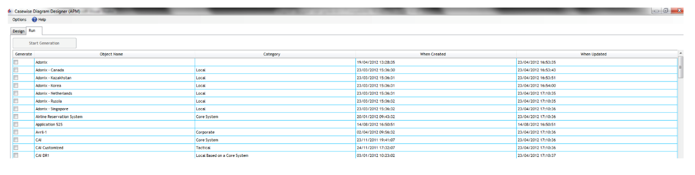
Run Mode for Single Output Type
In the single mode output, a diagram will be created for each primary object you will select.
You can select an object by checking the Generate column (1st column).
When selected, the selected row’s state column will change, below the lists of the available states:
|
State |
Description |
|
Waiting for generation |
The row has been correctly selected, when ready you can then start the generation |
|
Generation in progress |
The diagram is under generation |
|
Generated |
The diagram has been generated; it can be open using the “Open Diagram” column. |
|
Clearing joiners & shapes |
The diagram has been opened and is being cleared, this take time depending on the number of shapes and joiners you have on the diagram. |
Once at least one object is selected, you will be able to use the “Start Generation” button and start the generation of the diagram(s).
When a generation finishes, the name of the diagrams appears in the “Open Diagram” column, which should be the last column. You may then click once (like a hypertext link in your browser) and the diagram will open in Modeler.
Run Mode for Group Output Type
In the group mode for the group output type, all the objects you are going to select will be displayed on the diagram.
You can select an object by checking the Generate column (1st column).
Once you have selected at least one object, you can then use the “Start Generation” button to create the diagram.
When the generation starts, a new button appears labeled “Generation under progress”.
When the diagram is generated the button changes to “Open the Diagram”, if you click it, the diagram will open in Modeler.
You can go back at any time to the Design mode, and return, and your selected items will remain checked.
Related Items