
DR4300 system overview
Front panel features and indicators
Back panel features
Diagnostic indicators on the front panel
Technical specifications
Hard drive indicator codes
NIC indicator codes
Power supply unit indicator codes
iDRAC Direct LED indicator codes
Quick Sync indicator codes
Locating Service Tag of your system
Documentation matrix
Chassis dimensions
Chassis weight
Processor specifications
PSU specifications
System battery specifications
Expansion bus specifications
Memory specifications
Drive specifications
Ports and connectors specifications
Video specifications
Environmental specifications
Initial system setup and configuration
Setting up your system
iDRAC configuration
Options to install the operating system
Manage your system
Pre-operating system management applications
Options to manage the pre-operating system applications
System Setup
Installing and removing system components
Viewing System Setup
System Setup details
System BIOS
Dell Lifecycle Controller
Boot Manager
PXE boot
Viewing System BIOS
System BIOS Settings details
Boot Settings
Network Settings
System Security
iDRAC Settings utility
Device Settings
Viewing System Security
System Security Settings details
Secure Boot Custom Policy Settings
Creating a system and setup password
Using your system password to secure your system
Deleting or changing system and setup password
Operating with a setup password enabled
System Information
Memory Settings
Processor Settings
SATA Settings
Integrated Devices
Serial Communication
System Profile Settings
Miscellaneous Settings
Safety instructions
Before working inside your system
After working inside your system
Recommended tools
Front bezel (optional)
System cover
Cooling shroud
Cooling fans
Cooling-fan assembly
System memory
Using system diagnostics
Jumpers and connectors
Troubleshooting your system
General memory module installation guidelines
Mode-specific guidelines
Processors and heat sinks
PCIe card holder
Advanced Error Correction Code (lockstep)
Memory optimized (independent channel) mode
Memory sparing
Memory mirroring
Sample memory configurations
Removing memory modules
Installing memory modules
Removing the PCIe card holder
Installing the PCIe card holder
Opening and closing the PCIe card holder latch
Cable retention bracket
Integrated storage controller card
Expansion cards and expansion card riser
Expansion card installation guidelines
Removing an expansion card from expansion card riser 2 or 3
Installing an expansion card into the expansion card riser 2 or 3
Removing an expansion card from the expansion card riser 1
Installing an expansion card into the expansion card riser 1
Removing the riser 1 blank
Installing the riser 1 blank
Removing expansion card risers
Installing expansion card risers
Internal dual SD module (optional)
Removing an internal SD card
Installing an internal SD card
Removing the optional internal dual SD module
Installing the optional internal dual SD module
Network daughter card
Internal USB memory key (optional)
System battery
Power supply units (PSU)
Hot spare feature
Removing the power supply unit blank
Installing the power supply unit blank
Removing an AC power supply unit
Installing an AC power supply unit
System board
Trusted Platform Module
Installing the Trusted Platform Module
Initializing the TPM for BitLocker users
Initializing the TPM for TXT users
Hard drives
Removing a 2.5 inch hard drive blank (rear)
Installing a 2.5 inch hard drive blank (rear)
Removing a 3.5-inch hard drive blank
Installing a 3.5-inch hard drive blank
Removing a hot swappable hard drive or SSD
Installing a hot-swap hard drive
Removing a hard drive from a hard drive carrier
Installing a hard drive into a hard drive carrier
Hard drive backplane
Removing the hard drive backplane
Installing the hard drive backplane
Removing the optional hard drive backplane (rear)
Installing the optional hard drive backplane (rear)
SD vFlash card (optional)
Replacing an optional SD vFlash media card
Removing the vFlash media unit
Installing the vFlash media unit
Control panel assembly
Troubleshooting system startup failure
Troubleshooting external connections
Troubleshooting the video subsystem
Troubleshooting a USB device
Troubleshooting iDRAC Direct (USB XML configuration)
Troubleshooting iDRAC Direct (Laptop connection)
Troubleshooting a serial I/O device
Troubleshooting a NIC
Troubleshooting a wet system
Troubleshooting a damaged system
Troubleshooting the system battery
Troubleshooting power supply units
Troubleshooting cooling problems
Troubleshooting cooling fans
Troubleshooting system memory
Troubleshooting an internal USB key
Troubleshooting an SD card
Troubleshooting an optical drive
Troubleshooting a tape backup unit
Troubleshooting a hard drive
Troubleshooting a storage controller
Troubleshooting expansion cards
Troubleshooting processors
System messages
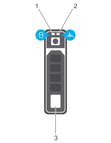
Hard drive indicator codes
Figure 3. Hard drive indicators
|
3. |
|
Drive ready for insertion or removal. | |||
|
Flashes green for three seconds, amber for three seconds, and then turns off after six seconds |
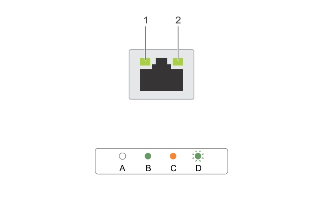
NIC indicator codes
Figure 4. NIC indicators
|
The NIC is connected to a valid network at its maximum port speed (1 Gbps or 10 Gbps). | ||
|
The NIC is connected to a valid network at less than its maximum port speed. | ||
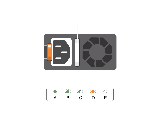
Power supply unit indicator codes
AC power supply units (PSUs) have an illuminated translucent handle that serves as an indicator and DC PSUs have an LED that serves as an indicator. The indicator shows whether power is present or a power fault has occurred.
Figure 5. AC PSU status indicator
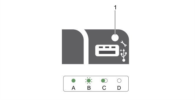
iDRAC Direct LED indicator codes
Figure 6. iDRAC Direct LED indicator
|
Turns green for a minimum of two seconds to indicate the start and end of a file transfer. | ||
|
Indicates that the USB is ready to be removed or that a task is complete. |