- VGA port and your video monitor
- USB port and your keyboard
DR4000
To make local console cable connections for the DR Series system appliance, complete the following steps.
- Locate the VGA monitor port and the USB ports on the back of your system. See Figure 3 for the VGA and USB port locations and complete steps 1 to 4. For the DR4100/DR6000 system, skip to step 5.
- Connect the video monitor to the VGA port on the back of your system (see item 1 in the DR4000 System Rear Chassis Port Locations table).
- Connect the USB keyboard to one of the two USB ports on the back of your system (see item 3 in DR4000 System Rear Chassis Port Locations table).
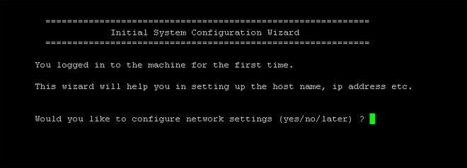
- You are now ready to perform initialization using the DR Series system CLI login process. For more information, see Logging in and Initializing the DR Series System.
Figure 8: DR4000 System Rear Chassis Port Locations
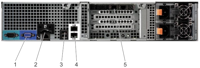
| Item | Indicator, Button, or Connector | Icon | Description |
|---|---|---|---|
| 1 | Video connector |  |
Connects a VGA display to the system. |
| 2 | iDRAC6 Enterprise port |  |
Dedicated management port for the iDRAC6 Enterprise card. |
| 3 | USB connectors (2) |  |
Connects USB devices to the system. The ports are USB 2.0-compliant. |
| 4 | Ethernet connectors (2) |  |
Embedded 10/100/1000 NIC connectors. |
| 5 | Ethernet Connectors (2) on expansion card | 1-GbE/10-GbE/10-GbE SFP+ Ethernet Port |
DR4100/DR6000
To make local console cable connections for the DR4100 or DR6000 system appliance, complete the following steps:
|
|
NOTE: For the 1–GbE ports, these are two internal LAN on Motherboard (LOM) ports referenced in item 4 above that reside on the motherboard, and two ports on an expansion card referenced in item 5 above. If the system is using the two 10–GbE ports, these reside on an expansion card referenced in item 5 above. |

- Locate the VGA monitor port and the USB ports on the back of your system. See Figure 3 for the VGA and USB port locations and complete steps 5 to 8.
- Connect the video monitor to the VGA port on the back of your system (see item 2 in the DR4100/DR6000 System Rear Chassis Port Locations table).
- Connect the USB keyboard to one of the two USB ports on the back of your system (see item 3 in the DR4100/DR6000 System Rear Chassis Port Locations table).
You are now ready to perform initialization using the DR Series system CLI login process. For more information, see Logging in and Initializing the DR Series System.
Figure 9: DR4100/DR6000 System Rear Chassis Port Locations
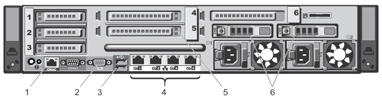
| Item | Indicator, Button, or Connector | Icon | Description |
|---|---|---|---|
| 1 | iDRAC7 Enterprise port | |
Dedicated management port for the iDRAC7 Enterprise card (port is available only if an iDRAC7 Enterprise license is installed on your system). |
| 2 | Video connector | |
Connects a VGA display to the system. |
| 3 | USB connectors (2) | |
Connects USB devices to the system. The ports are USB 2.0-compliant. |
| 4 | Ethernet connectors (4) | |
Four integrated 10/100/1000 NIC connectors, or four integrated connectors that include:
|
| 5 | PCIe expansion card slots (3) | Connect up to three full-height PCI Express expansion cards | |
| 6 | Hard drives (2) | Provides two hot-swappable 2.5-inch hard drives |
|
|
NOTE: The DR4100/DR6000 system supports up to six 1–GbE ports or up to two 10–GbE ports. For the 1–GbE ports, these are four internal LAN on Motherboard (LOM) ports referenced in item 4 above that reside on the network daughter card (NDC), and two additional ports on a PCI Express expansion card referenced in item 5 above. If the system is using the two 10–GbE ports, these ports reside on the NDC. |
DR4300e/DR4300/DR6300
To make local console cable connections for the DR4300e, DR4300, or DR6300 system appliance, complete the following steps:
- Locate the VGA monitor port and the USB ports on the back of your system. See Figure 3 for the VGA and USB port locations and then complete steps 10 to 12.
- Connect the video monitor to the VGA port on the back of your system (see item 6 in the DR4300e/DR4300/DR6300 System Rear Chassis Port Locations table).
- Connect the USB keyboard to one of the two USB ports on the back of your system (see item 7 in the DR4300e/DR4300/DR6300 System Rear Chassis Port Locations table).
- You are now ready to perform initialization using the DR Series system CLI login process. For more information, see Logging in and Initializing the DR Series System.
Figure 10: DR4300e/DR4300/DR6300 System Rear Chassis Port Locations
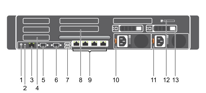
| Item | Indicator, Button, or Connector | Icon | Description | ||||||
|---|---|---|---|---|---|---|---|---|---|
| 1 | System identification button |  |
The identification buttons on the front and back panels can be used to locate a particular system within a rack. When one of these buttons is pressed, the system status indicator on the back flashes until one of the buttons is pressed again.Press the button to toggle the system ID on and off. If the system stops responding during POST, press and hold the system ID button for more than five seconds to enter BIOS progress mode. To reset iDRAC (if not disabled in F2 iDRAC setup) press and hold the button for more than 15 seconds. | ||||||
| 2 | System identification connector | Connects the optional system status indicator assembly through the optional cable management arm. | |||||||
| 3 | iDRAC8 Enterprise port | |
Dedicated management port for the iDRAC7 Enterprise card (The port is available for use only if the iDRAC8 Enterprise license is installed on your system.) | ||||||
| 4 | PCIe expansion card slots half height (3) |
Allows you to connect up to three half-height PCI Express expansion cards. | |||||||
| 5 | Serial connector |  |
Allows you to connect a serial device to the system. | ||||||
| 6 | Video connector | |
Connects a VGA display to the system. | ||||||
| 7 | USB connectors (2) |  |
Connects USB devices to the system. The ports are USB 3.0-compliant. | ||||||
| 8 |
PCIe expansion card slots full height (3) (Dell PowerEdge R730xd) |
Allows you to connect up to three full-height PCI Express expansion cards. | |||||||
| 9 | Ethernet connectors (4) | |
Four integrated 10/100/1000 Mbps Network Interface Card (NIC) connectors or four integrated connectors that include:
| ||||||
| 10 |
Power supply (PSU1) |
| |||||||
| 11 |
Power supply (PSU2) |
| |||||||
| 12 | vFlash media card slot |  |
Allows you to insert a vFlash media card. | ||||||
| 13 | Hard drives (2) (back) |
Allows up to two hot-swappable 2.5 inch hard drives. | |||||||