Chat now with support
Chat with Support

Foglight for Storage Management Shared 4.6 - User and Reference Guide

Getting Started Monitoring Storage Performance Investigating Storage Devices Investigating Storage Components Investigating VPLEX Storage Troubleshooting Storage Performance Managing Data Collection, Rules, and Alarms Understanding Metrics Online-Only Topics

Exploring Connectivity with SAN Topology Diagrams

SAN Topology diagrams map the connections through the virtual environment (VMs-to-virtualization storage-to-extents) to the resources in the SAN (LUNs and NASVolumes). Topology diagrams hide port-level details to focus on connectivity. Using this view, you can see which resources have an alarm status along each connection path, and begin to form hypotheses about whether or not the SAN environment is contributing to performance issues in the virtual environment. You can then drill down on resources to test those hypotheses.

In a topology diagram, you can view individual port connections by clicking one or more cloud icons. Details are shown in a separate window.

The SAN Topology view displays as a graph for a VM, Datastore or CSV, and for a storage LUN or NASVolume.

The SAN Topology view for a Cluster or server or host will offer the following choices for viewing the topology:

The option to show all storage resources as a table will include Datastores or CSVs that are not used by VMs.

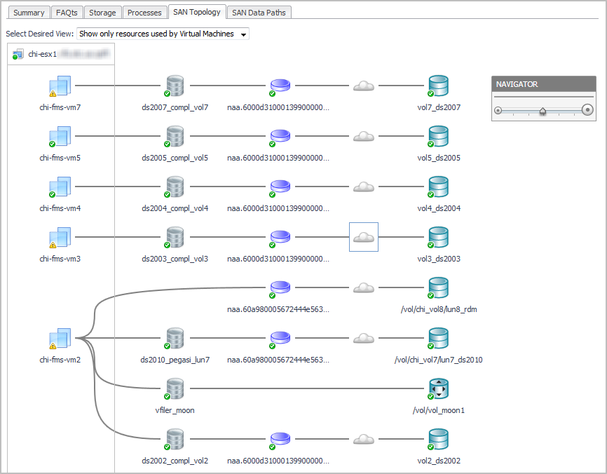
The following workflow explains how you can verify connectivity and the status of entities and storage devices in your infrastructure using a topology diagram. This procedure assumes that you navigated to a topology view from a Virtualization Explorer dashboard (see Introducing the Virtualization Dashboards) or from a Storage Explorer component dashboard (see Investigating a LUN or Investigating a NASVolume).

5
Click a Cloud icon to display the ports and SAN paths from the logical storage to the LUN, through the host or server.

Exploring I/O Performance with SAN Data Paths

The SAN Data Paths tab focuses on input/output performance of the ports used in the data paths connecting the virtual environment to the SAN. This view combines an I/O Data Paths table with a topology diagram that includes port details and I/O performance metrics. The table displays the worst-performing path segment of the possible data paths between each disk extent and the LUN during the time period, helping you to identify bottlenecks resulting in high latency. The diagram enables you see the entities that are capable of doing I/O through each path segment, corresponding to the table rows.

Because the metric values in the SAN Data Paths tab represent the average values over the time period, consider selecting a shorter time range (one hour or less) to help investigate performance spikes. For example, if a customer is complaining about latency issues in the last 15 minutes, you may want to set the dashboard time range to the last 15-30 minutes to focus on the problem period.

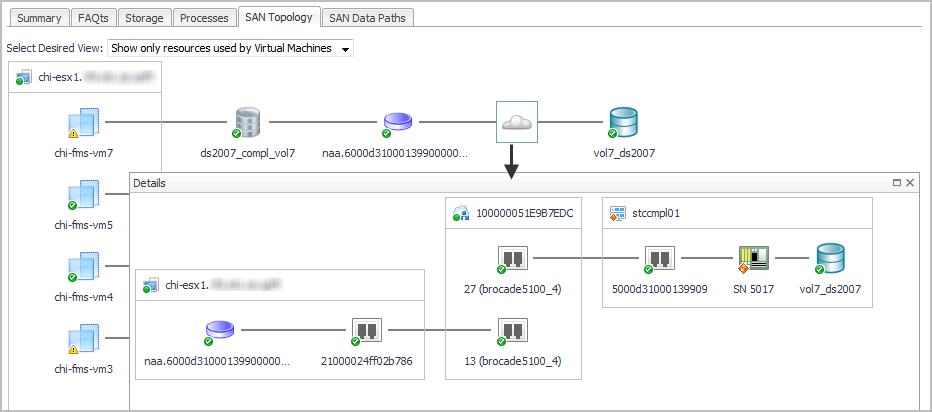
This workflow walks you through using the SAN Data Paths tab from the VMware Explorer’s ESX Host dashboard. The content of the SAN Data Paths tab may be slightly different on the Virtual Machine, Datastore, and LUN dashboards, but the flow is the same. The workflow for Hyper-V servers, VMs, and CSVs is similar, but uses the Hyper-V terminology. This workflow continues from Introducing the Virtualization Dashboards.

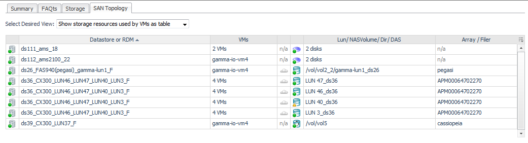
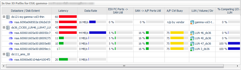
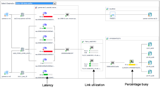
Datastore/Disk Extent. List of datastores and the disks that they use, ordered so that the datastores with high-latency disk extents appear at the top. Datastores configured from a NASVolume show only the associated volume; no other data is available. If an RDM or Other node is displayed, the disk extents under this node are RDMs providing storage directly to the virtual machine.
Latency. Average latency per operation.
Data Rate. Average data rate for I/O from the ESX or VM to the LUN.
ESX FC Ports --> SAN Util. Displays the busiest link (read or write utilization) in the possible paths between the ESX and the FC switches. Click the cell to display all the port links. Review the topology diagram to see the ports and link utilization. Data is not available for IP ports.
SAN --> A/F Ports Util. Displays the busiest link (read or write utilization) in the possible paths between the FC switches and the array/filer ports. Click the cell to display all the port links. Review the topology diagram to see the ports and link utilization. Data is not available for IP ports.
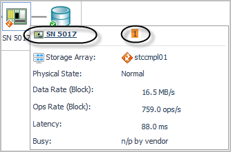
A/F Ctrl Busy. Displays the CPU % Busy metric for the busiest controller in the data path for a storage array or filer. % Busy values are not available on some devices.
LUN / NASVolume / Dir. Displays the LUN that is mapped to the extent, or displays the NASVolume (filers) or directory (Isilon arrays) providing the storage for a datastore.
% Competing I/O at LUN. Displays the percentage of I/O being experienced by this LUN for all VMs accessing the Datastore, not just those in this ESX. Click the cell to display the top five VMs doing I/O to this LUN.
LUN State. Reports on the state of the LUN as follows:
Table 6. LUN states

Indicates that the LUN is reporting activity that gives an indication of performance problems, it is currently degraded or rebuilding, or the % Busy or Latency metrics are over their thresholds for the time period. Dwell on the cell for details.

Indicates that the vendor does not provide % Busy or Latency metrics.

Indicates that either the % Busy metric or Latency metric is within normal range during the time period, and the LUN is not reporting that it is currently degraded or rebuilding. Dwell on the cell for details.

Latency (ms). Average latency per operation to the LUN during the time period.
Latency: VMW:diskTotalLatency.[warning|critical|fatal]
Latency: HPV:diskTotalLatency.[Warning, Critical, Fatal]
Port utilization: StSAN.FCSwitchPort.Utilization.[Warning|Critical|Fatal]
A/F Ctrl Busy: StSAN.Controller.PctBusyThreshold.[Warning|Critical]

Monitoring Storage Capacity

Foglight for Storage Management closely monitors the capacity being used by the pools in your array or filer. The historical growth of pool capacity usage is analyzed daily to estimate how much time is remaining until the pool becomes full. This capability is critically important for pools that are over-committed with thin-provisioned LUNs and/or NASVolumes.

This section discusses the rules and alarms, views, charts, reports, and configurable values you can use to monitor your pool capacity.

For details, see the following topics:

Capacity Trending

Foglight for Storage Management performs a linear regression analysis nightly on the historical values of consumed pool capacity.

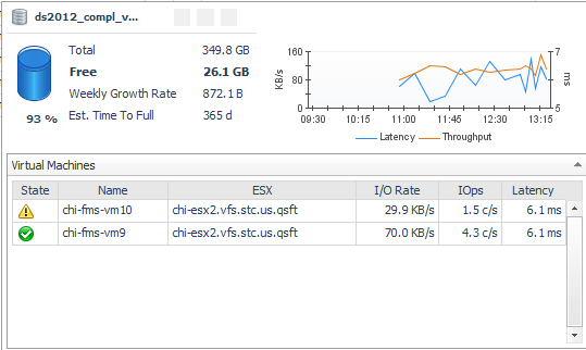
The Time Until Full (per available history) will use all available history, up to the last 180 days, to project when the pool will become full. The minimum number of days required to compute this trend is defined by the registry variable StSAN_minDaysForLongHistTrend. The default is 30 days.

The Time Until Full (per limited history), will use only recent history, up to the last 30 days, to project when the pool will become full. The minimum number of days required to compute this trend is defined by the registry variable StSAN_minDaysForShortHistTrend. The default is 20 days. Examining this value is useful primarily when there has been a significant recent change in the pool usage that is expected to continue.

The Time Until Full value is displayed with the following granularity:

The Time Until Full (available history) value is displayed on most screens that show pool date. The Capacity tab of a Pool Explorer will display a chart of the capacity and the trends.

Related Documents

The document was helpful.

Select Rating

I easily found the information I needed.

Select Rating