Configuring Drafts and Publishing Diagrams
This page explains how to configure Drafts and Publish diagrams in Web Modeler.
Add the Publish and Drafts tabs to your Object Page:
|
|
These instructions detail how to add the built-in tabs to control draft diagrams, to an Object Page. Unlike other elements in Evolve, these tabs are limited to Object Pages, and all diagrams must be associated to an Object. |
To add the tabs to an Object Page:
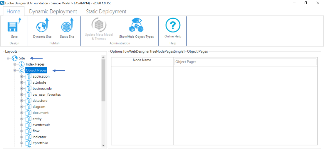
1.Logon to the site
2.Expand Site and Object Pages
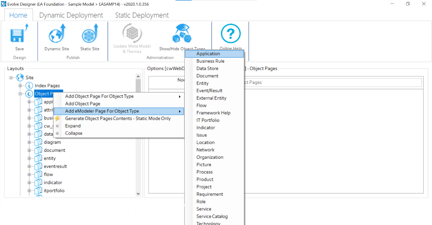
3.Right-click on Object Pages, hover on Add eModeler Page for Object Type.
4.Select the object type you wish to create diagrams against, e.g. Application.
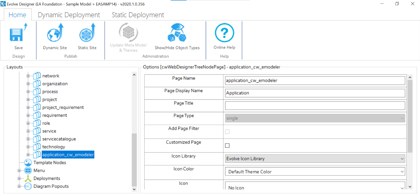
5.Scroll down to see <object-type>_cw_emodeler, e.g. application_cw_emodeler and click on it.
6.Change
- Page Display Name to Web Modeler
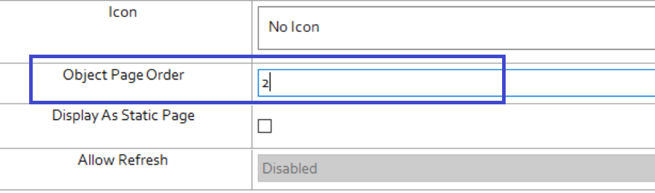
- Object Page Order to 2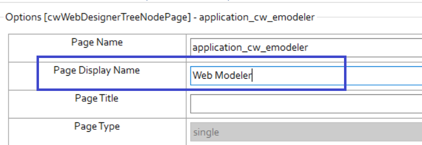
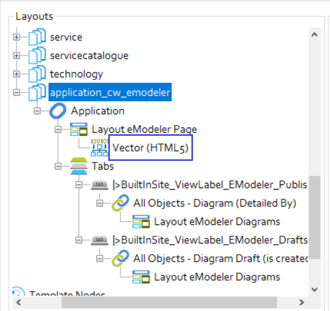
7.Further, expand <object-type>_cw_emodeler, e.g. application_cw_emodeler, to display the Layout eModeler Page and Tabs with sub-tabs.
8.Click Vector (HTML5)
Configuring Diagram Popouts for Draft Diagrams:
In order to edit more object properties than the basic ones, you will need to configure a Diagram Popout.
See here, for Diagram Popout configuration. Then, to enable this Popout for Web Modeler:
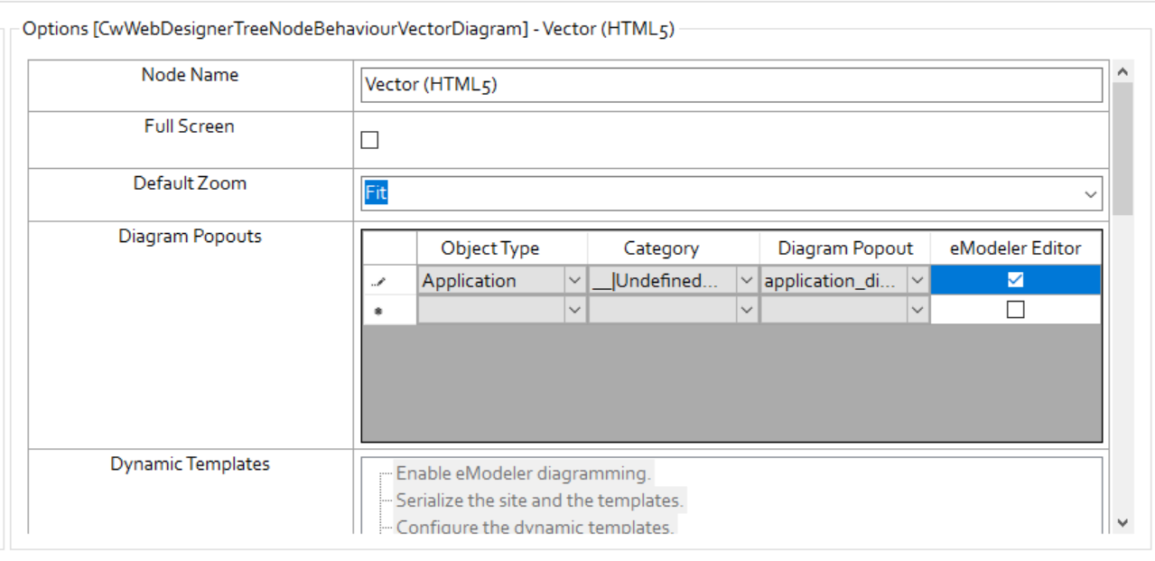
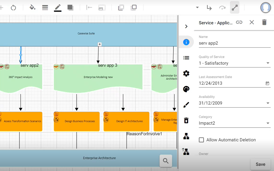
1.Go to Diagram Popouts, choose Object type as the object type that represents this diagram, e.g. Application, click on Category, if your Popout is defined correctly, it should fill out the fields automatically as they are predefined by the Popout.
Check eModeler Editor.
|
|
Note: Once the eModeler Editor is checked, it ensures that all these Popout properties are editable inside the Web Modeler application. |
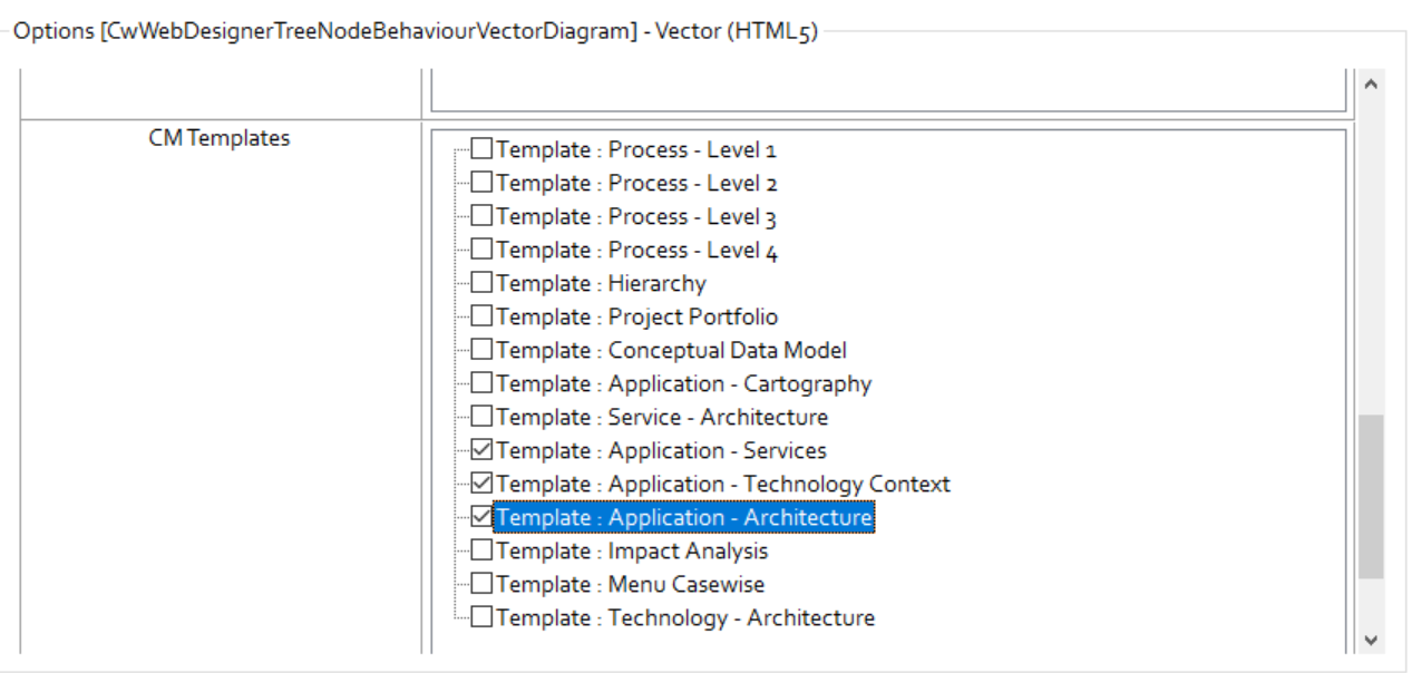
2.Scroll down to CM Templates.
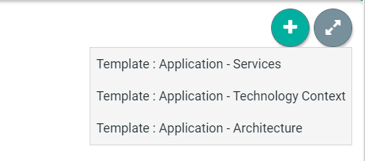
Check the templates you wish to associate with this Web Modeler page, e.g. – Application – Services, Application – Technology Context and Application – Architecture
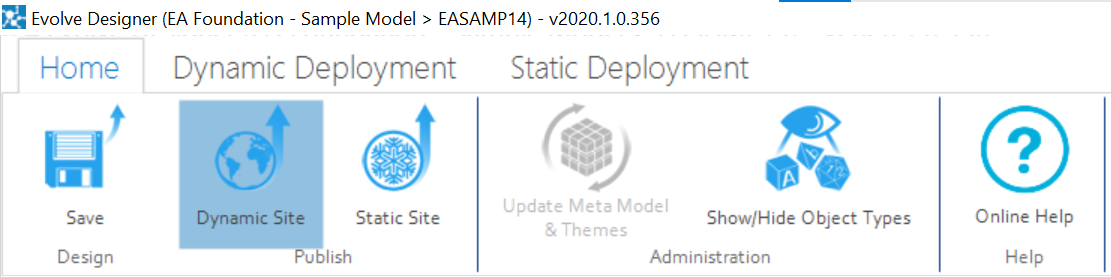
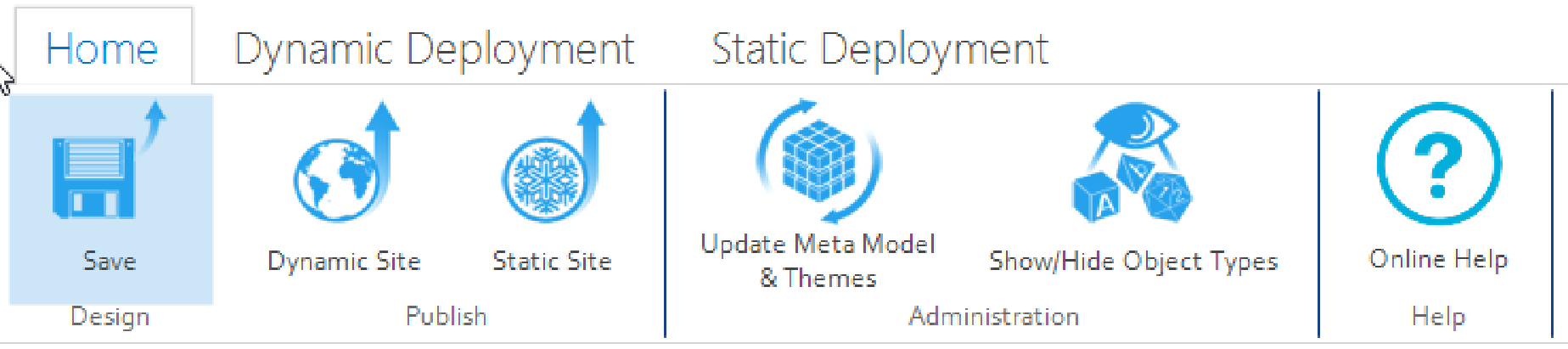
Click on Save under the Home tab and then click on Dynamic Site to generate the site.
Drafts and Published Diagrams in Web Modeler:
|
|
Drafts and Published are the two tabs under the Web Modeler menu. This section can be viewed only when the Web Modeler has been setup in Evolve Web Platform. |
To view Drafts and Published Diagrams in Web Modeler.
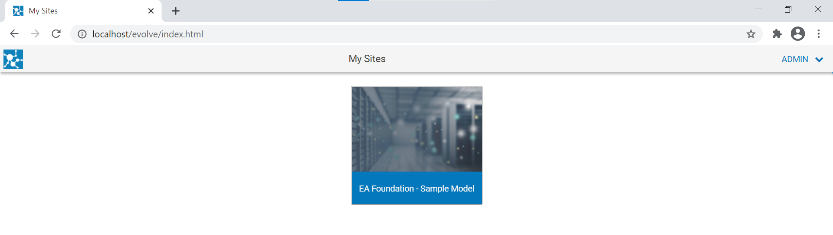
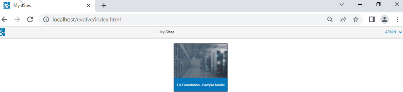
1.Open the browser and login to Evolve.
Select your Model, e.g. EA Foundation – Sample Model
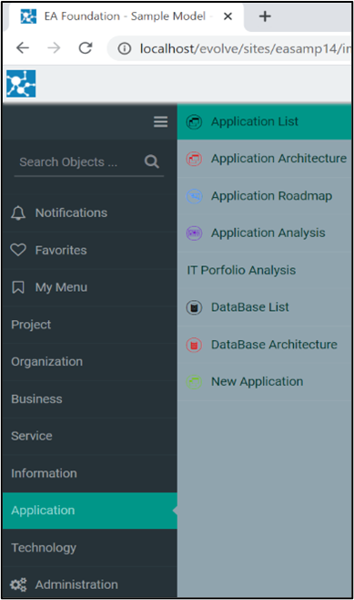
2.Go to the page you configured.
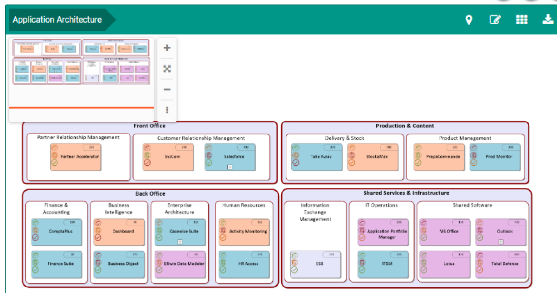
e.g. From the sample, Application from the left menu. Click Application List.
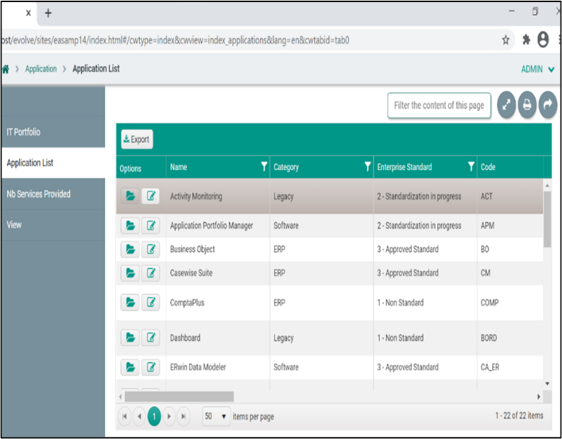
Choose the desired application from the list.
For instance, choose the first application from the list in the picture.
|
|
|
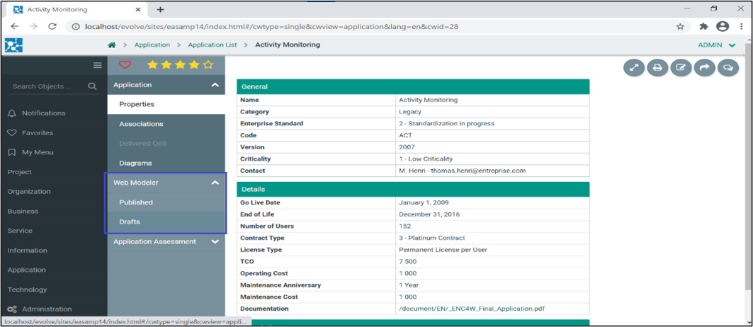
3.The new tab will be visible in your Object Page, e.g. Web Modeler.
Under the drop-down menu Web Modeler,
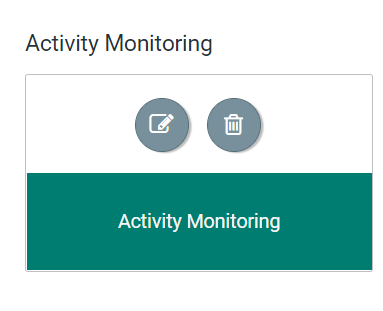
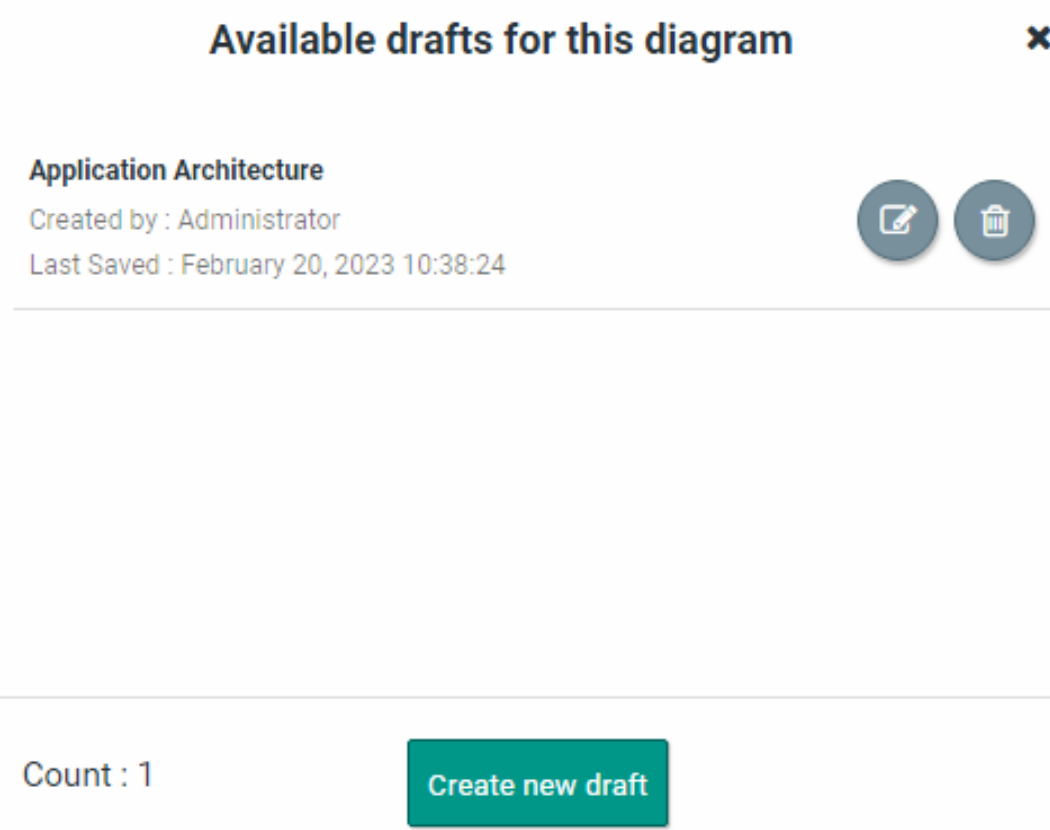
oDrafts – Collection of saved diagrams are displayed under tab Drafts. Initially this will be empty. Each time you press the Save button in Web Modeler, the draft will be updated in Evolve. Note that this is not the same as Publishing; a draft is a diagram in a transitional state. When a draft is published, it becomes a real Evolve diagram, and the objects it contains are updated in the Evolve Model.
Each Draft has controls that allow you to Edit and to open the diagram in the Object Page.
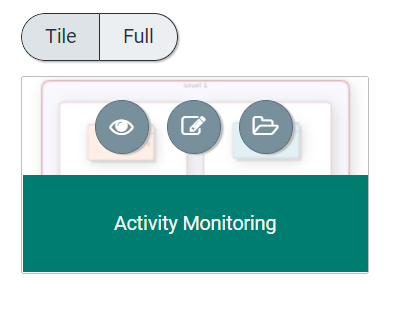
oPublished – Collection of all published diagrams are displayed under tab Published.
Each published diagram has controls that allow to View, Edit, and open the diagram in the Object Page.
Creating and Publishing a new Diagrams using Web Modeler:
1.To create and publish a new diagram, go to tab Published (initially the space under the tab shows as empty).
Click on 
Choose the desired template to start creating the new diagram.
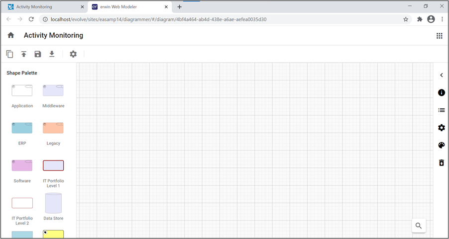
Evolve Web Modeler editor opens in the new tab with the predefined Shape Palette of the template chosen.
2.To publish the diagram, press the 
Once the diagram is published in the Web Modeler, the same diagram can be accessed from Modeler in the desktop application.
|
|
A Diagram and Palette properties can be modified if required from the desktop application. |
To set the Parent object and object name in Evolve Web:
|
|
Before setting the Parent object and Parent object name in Erwin Evolve web, first, we need to enable these options (Parent object and Parent object name) in Evolve Designer and publish them on the site. |
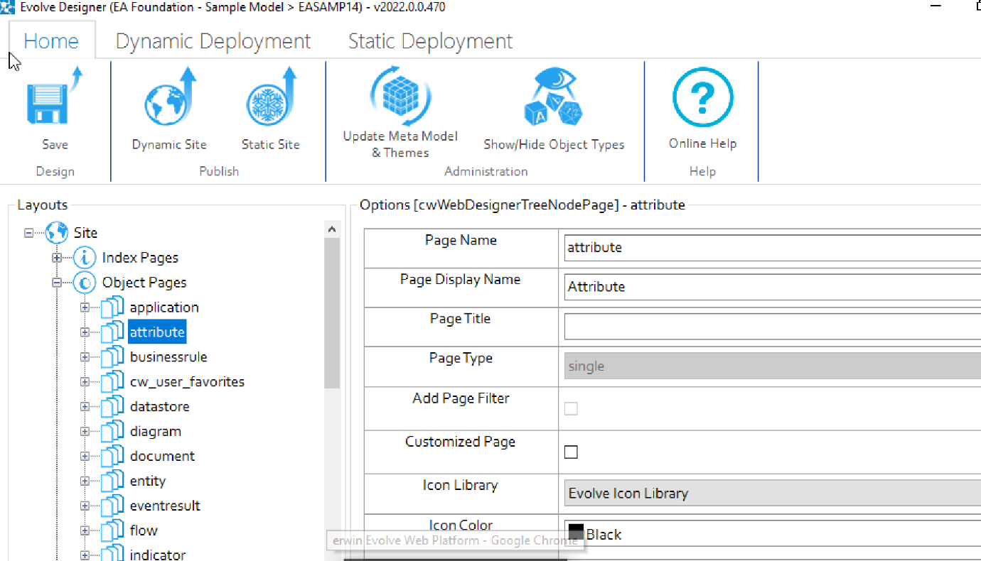
To enable the Parent Object in Evolve Designer:
1.Run the Evolve Designer.
2.Click on the model, e.g., EA Foundation – Sample Model.
3.Click Site.
4.Expand Site and Object Pages.
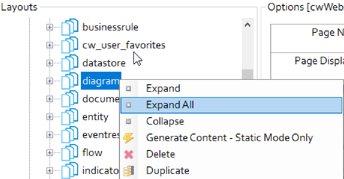
5.Right-click on the diagram and click Expand All.
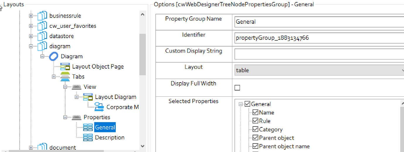
6.Click General, check the Parent object and Parent object name box.
7.Click Save and then, click Dynamic Site to generate the site.
To set the Parent object and object name in Evolve Web
1.Open the browser and login to Evolve.
2.Click on the model, e.g., EA Foundation – Sample Model.
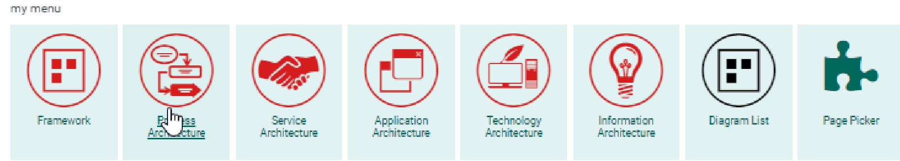
3.Click Diagram List from my menu.
The Diagram list appears.
4.Search the diagram name in Filter the content of this page box.
5.Click Open related object page icon.
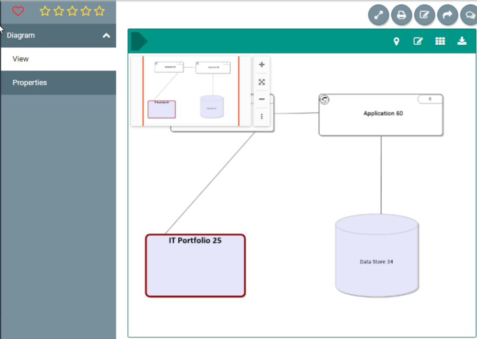
The diagram will be visible on your object page.
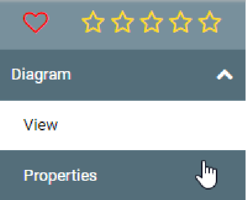
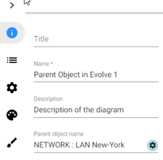
6.Click Properties under Diagram dropdown.
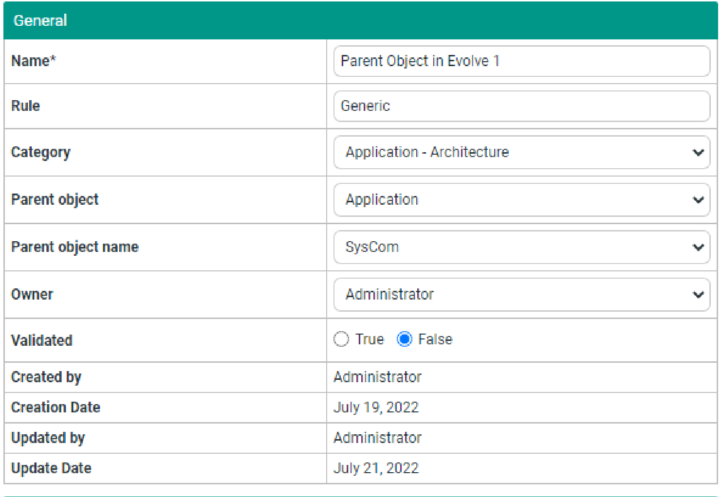
7.Click Edit icon to edit the Parent object and Parent object name.
8.Click Parent object dropdown and select required option.
9.Click Parent object name dropdown and select required option.
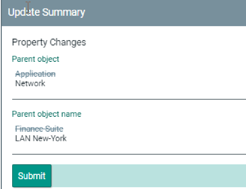
10.Click Save changes icon.
The Update summary pane appears on right-hand side.
11.Click Submit.
To set Parent object and object name in Web Modeler
1.Click View under Diagram dropdown.
2.Click Edit Diagram In Web Modeler icon.
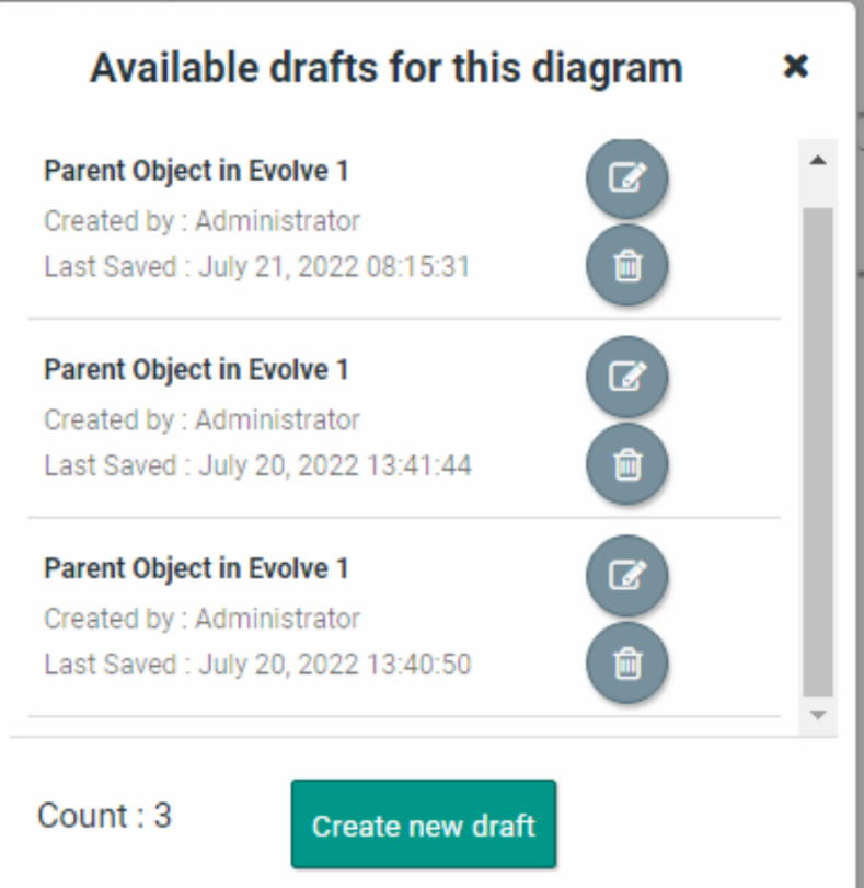
3.Click Create new draft.
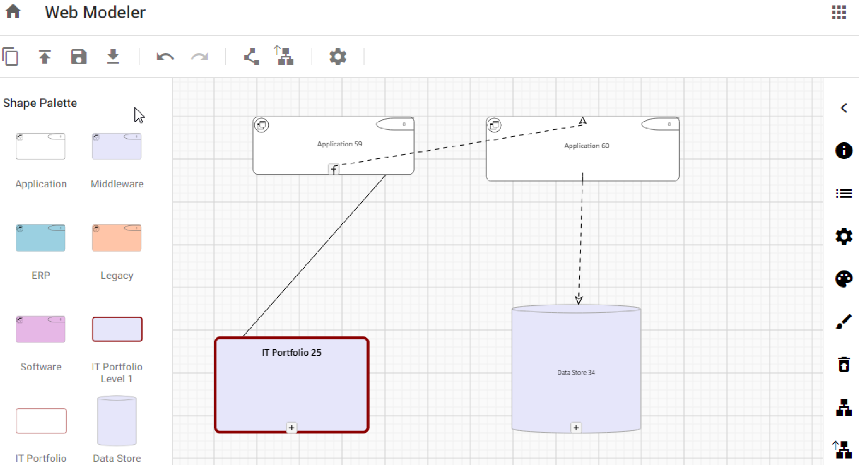
Evolve Web Modeler editor opens in the new tab with the predefined Shape Palette of the template chosen.
4.Click on 
5.Click on 
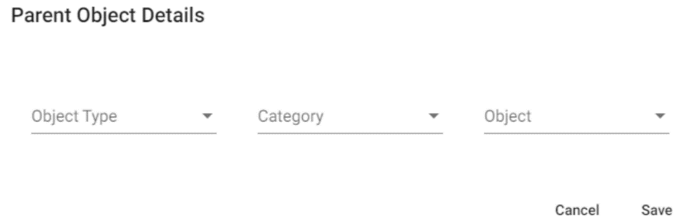
Parent Object Details popup opens.
6.Click Object Type dropdown and select the required option.
7.Click Category dropdown and select the required option.
8.Click Object dropdown and select the required option.
9.Click Save.
To publish the diagram:
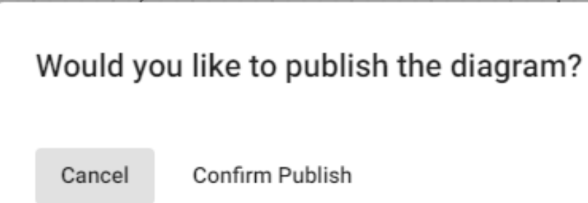
1.Click Publish Diagram icon.
2.Click Confirm Publish.
Once the diagram is published in the Web Modeler, it can be accessed from the Modeler in the desktop application.
|
|
A Diagram and Palette properties can be modified if required from the desktop application. |
Configuring Diagram Properties
You can use the Diagram Popout object in Evolve Designer to configure diagram properties other than the default ones. Once configured, these properties are then visible in erwin Web Modeler under diagram properties.
To configure Diagram Popout in Evolve Designer:
1.Start Evolve Designer.
2.Click a model. For example, EA Foundation - Sample Model.
3.Click Site.
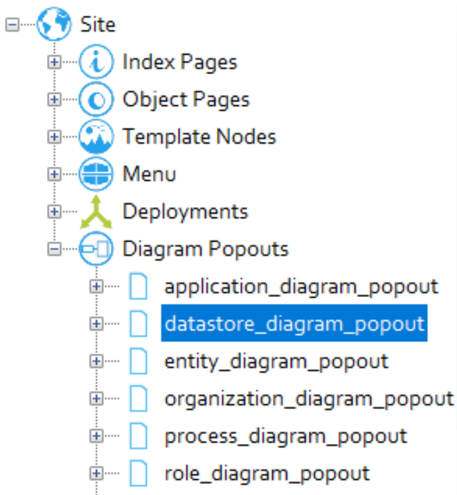
4.Expand Site > Diagram Popouts.
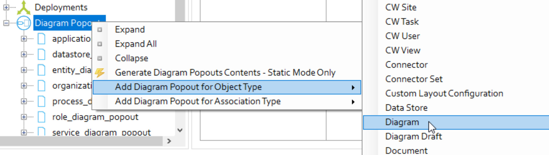
5.Right-click Diagram Popout and click Add Diagram Popout for Object Type > Diagram.
The Diagram Popout is created for the Diagram object type.
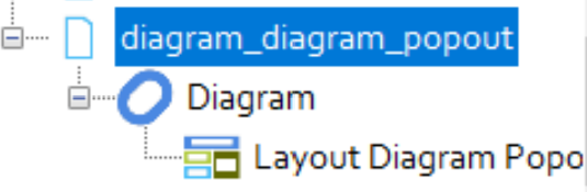
6.Expand diagram_diagram_popout.
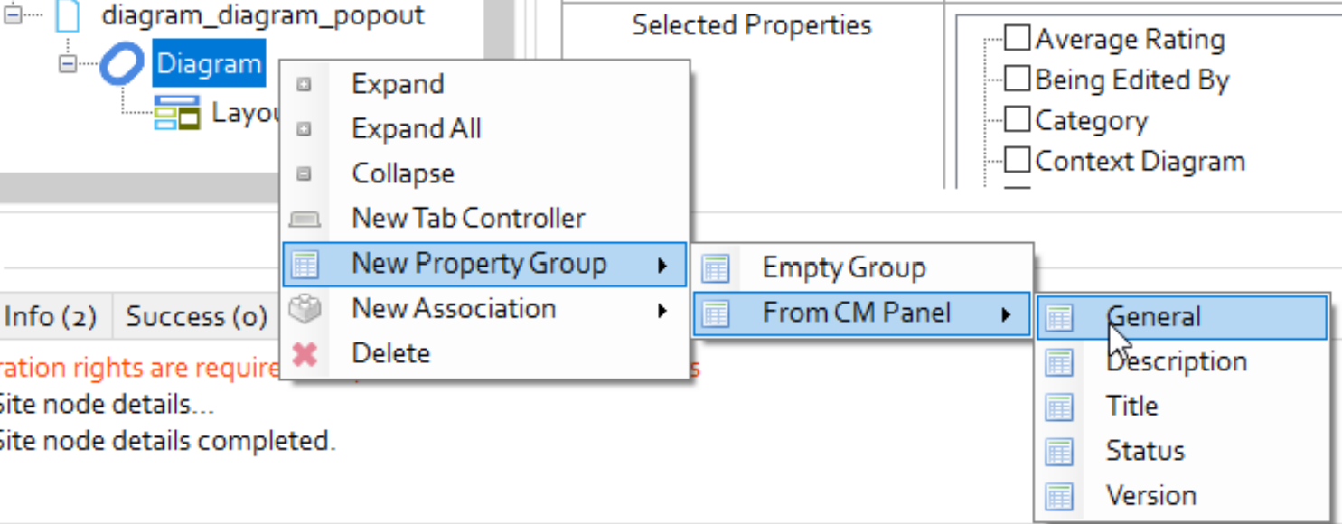
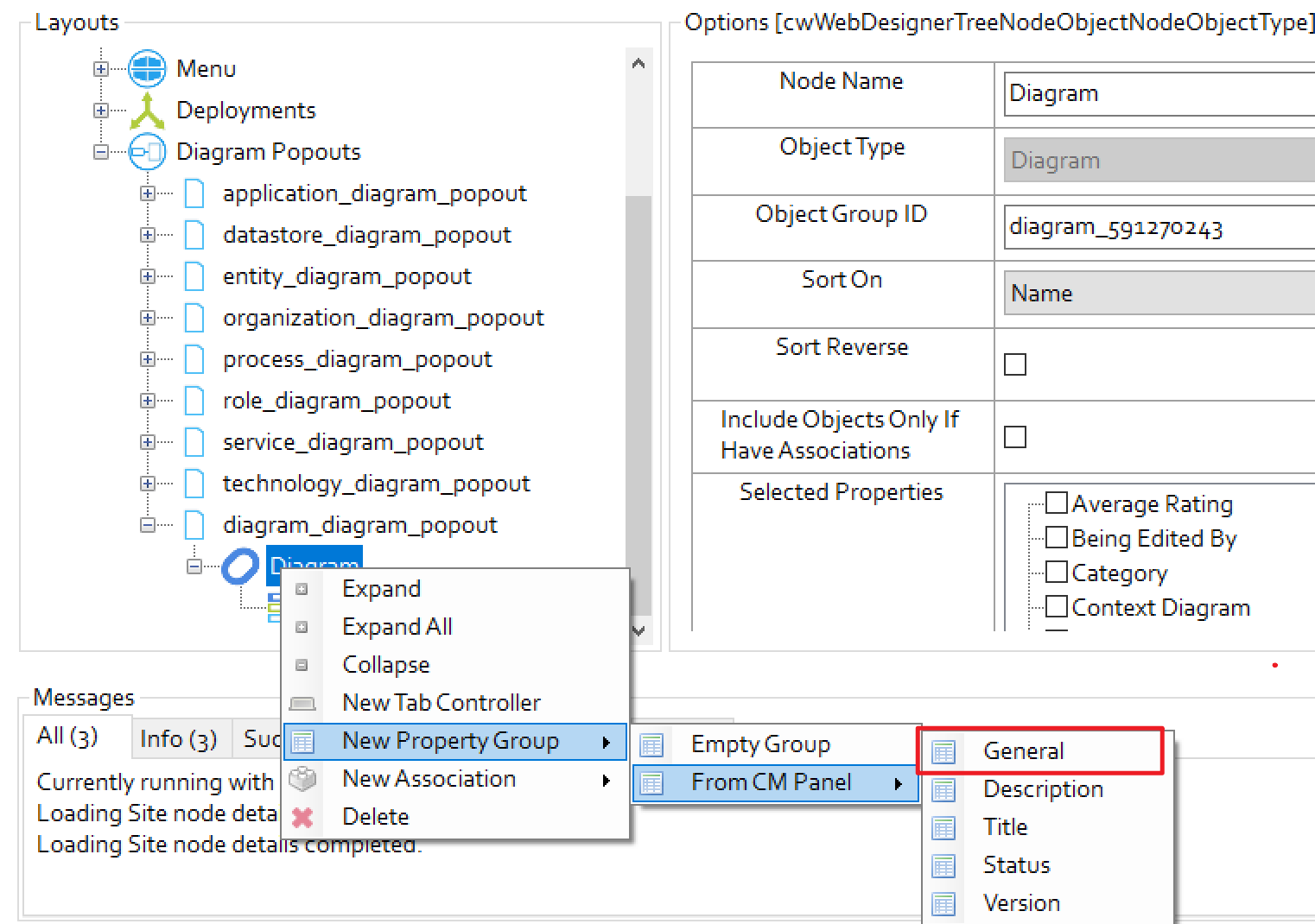
7.Right-click Diagram and click New Property Group > From CM Panel > General.
|
|
You can add any Property Group that you want to display in erwin Web Modeler. |
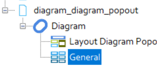
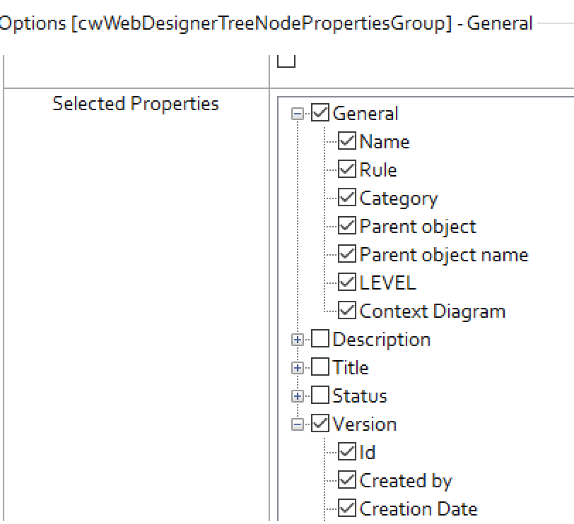
8.Click General.
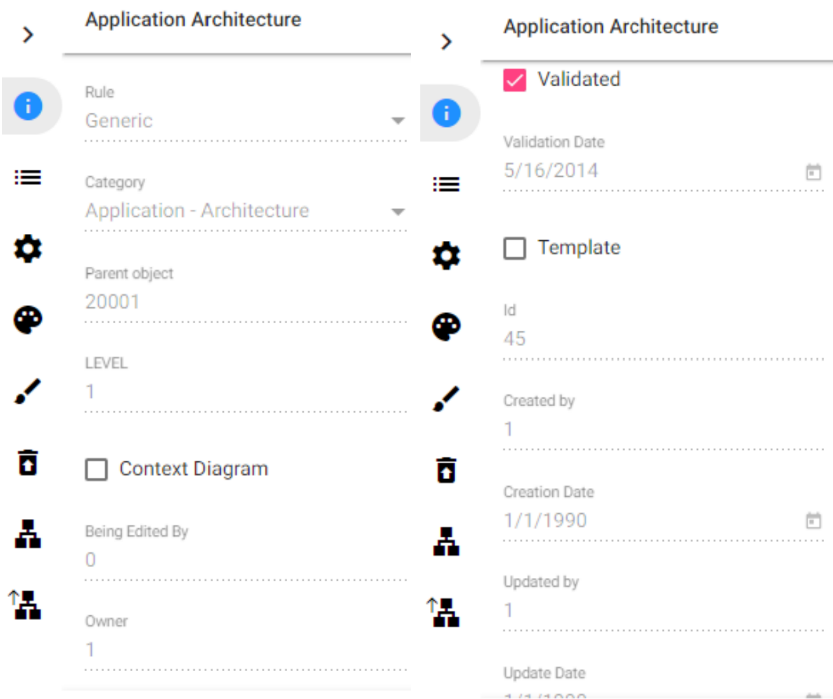
9.Under Selected Properties, select the properties that you want to display as diagram properties in erwin Web Modeler.
10.Click Save.
11.Click Dynamic Site.
|
|
The newly configured diagram properties are available only for new and duplicate drafts. |
To view the newly configured properties in erwin Web Modeler:
1.Click the Edit Diagram In Web Modeler icon.
2.Click Create new draft.
The erwin Web Modeler editor opens in a new tab with the predefined Shape Palette of the template chosen.
3.Click 
The properties that you selected in Evolve Designer are now visible under diagram properties.
To update the properties in erwin Web Modeler:
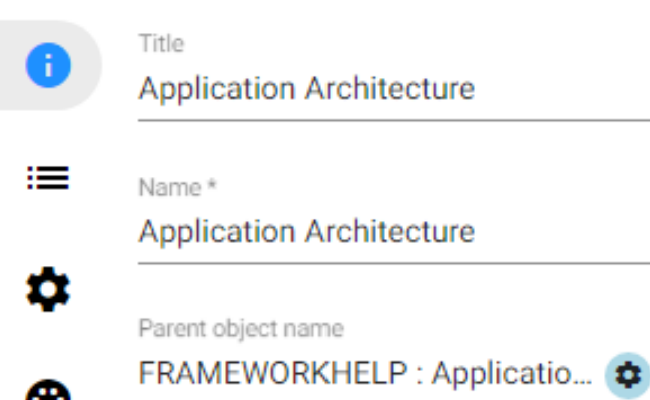
1.Click the required property that you want to update. For example, Title.
2.Update the Title and click 
3.Click Confirm Publish.
The Title is updated.
Similarly, you can view and update properties for duplicate drafts.
|
|
The newly configured diagram properties are available only for new and duplicate drafts. |
In erwin Web Modeler, you can now edit or set the properties of association objects and lines during diagram creation.
To achieve this, you must first create and configure the diagram pop-out and then link it to the diagram.
To configure Diagram Popout in Evolve Designer:
1.Start Evolve Designer.
2.Click a model. For example, EA Foundation - Sample Model.
3.Click Site.
4.Expand Site > Diagram Popouts.
5.Right-click Diagram Popout and click Add Diagram Popout for Object Type > Diagram.
The Diagram Popout is created for the Diagram object type.
6.Expand diagram_diagram_popout.
7.Right-click Diagram and click New Property Group > From CM Panel > General.
|
|
You can add any Property Group that you want to display in erwin Web Modeler. |
8.Click General.
9.Under Selected Properties, select the properties that you want to display as diagram properties in erwin Web Modeler.
10.Click Save.
11.Click Dynamic Site.
|
|
The newly configured diagram properties are available only for new and duplicate drafts. |
To create a diagram popout:
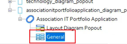
1.Right-click association type.
2.Go to New property Group > From CM Panel > General.
You can see General is added to the node.
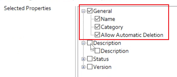
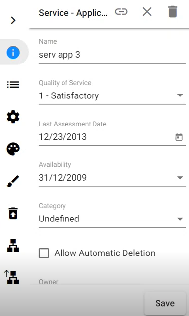
Also, it has some properties such as, Name, Category, and Allow Automatic Deletion.
The configuration of properties is same for the current object popouts. For example, in the above image, the group, General is selected and it has a name, category, and allow automatic deletion properties selected.
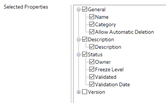
You can also select multiple property groups. For example, in the below image, the group, General, Description, Status is selected.
Once the diagram popout is created. We need to assign it to the diagram.
To assign this diagram popout to the diagram:
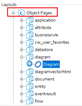
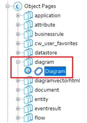
1.Expand Object Pages node.
2.Expand Diagram node.
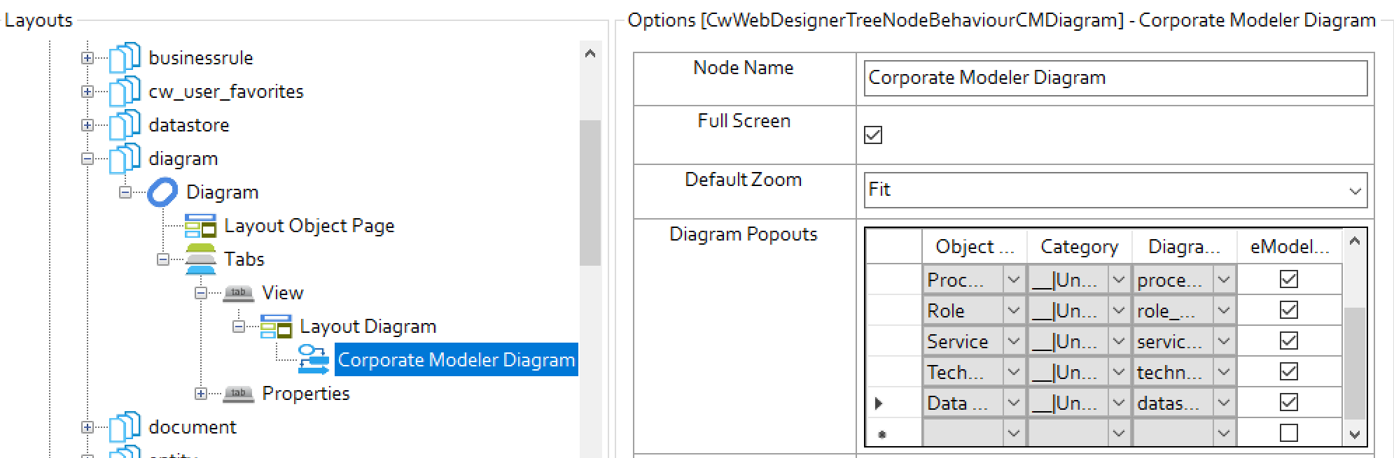
3.Go to Diagram > Tabs > View > Layout Diagram > Corporate Modeler Diagram.
In the diagram popout, you can see list of available association type with category, diagram popout, and eModeler Editor.
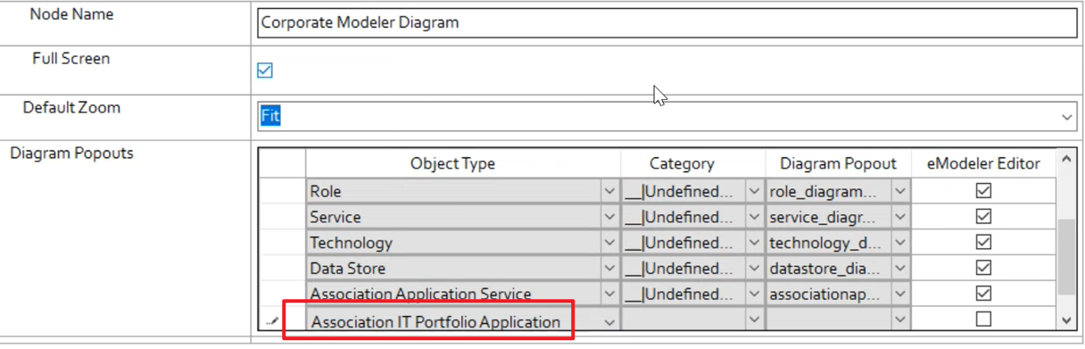
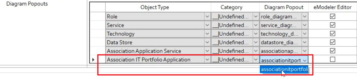
4.Select the association type from the Object Type drop-down. For example, Association IT Portfolio Application.
Based on the above selection, Category and Diagram Popout appears.
5.Select the eModeler Editor check box.
The diagram popout is available in erwin Web Modeler.
Now, when you open the diagram in erwin Web Modeler and select any line, you can see and edit all the properties.
To update the association properties in erwin Web Modeler:
1.Click the required property that you want to update. For example, Name.
2.Update the Name and click Save.
3.Click
4.Click Confirm Publish.
The Title is updated.
Formatting Shapes In Web Modeler
|
|
Please check with your Administrator that firstly, your Server and Internet Browser meet the necessary system requirements to use Web modeler. Secondly, check with your Administrator that the Web Modeler feature is enabled. |
This page explains how to format shapes in the Web Modeler online step by step.
Adding Shapes, Connecting Lines To The Diagram, and Changing Properties
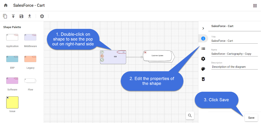
To add shapes to the diagram,
1.Drag and drop the required shape from the Shape Palette.
2.Double-click on the object shape to edit the Title and its Properties.
3.Click Save.
You can use a Connector to link two Shapes, indicating that there is a connection between the two shapes.
In-Place editing in the shape,
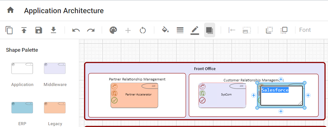
You can edit the name of a shape in the diagram editor using In-place editing.
To edit the name of the shape,
1.Select the shape you wish to edit.
2.Click again on the shape and then enter the text.
3.Either press Enter or click anywhere on the editor to finish editing.
To add the connector between the shapes,
1.Select the first shape by clicking on it.
2.Click on one of the + symbols to add the connector and move your mouse pointer to the shape you would like to connect to.
3.Click on the shape to end the selection.
4.If there are multiple connection types between these kinds of objects, you will get a menu to choose the connection that is appropriate.
To Clear or Delete Shapes from the Diagram
Object Shapes can be Cleared or Deleted from the diagram in two ways.
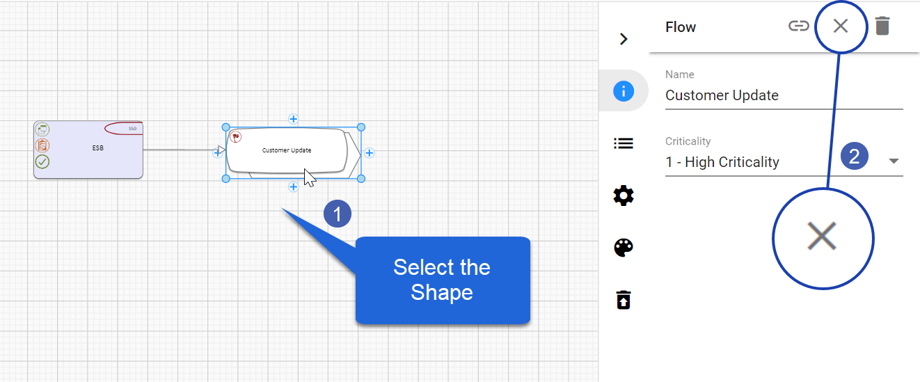
To Clear a Shape:
When you choose to Clear a shape, it removes the shape from the diagram, but it does not remove the object it represents from the model.
1. Select the shape you wish to Clear.
2. Click on 
Or
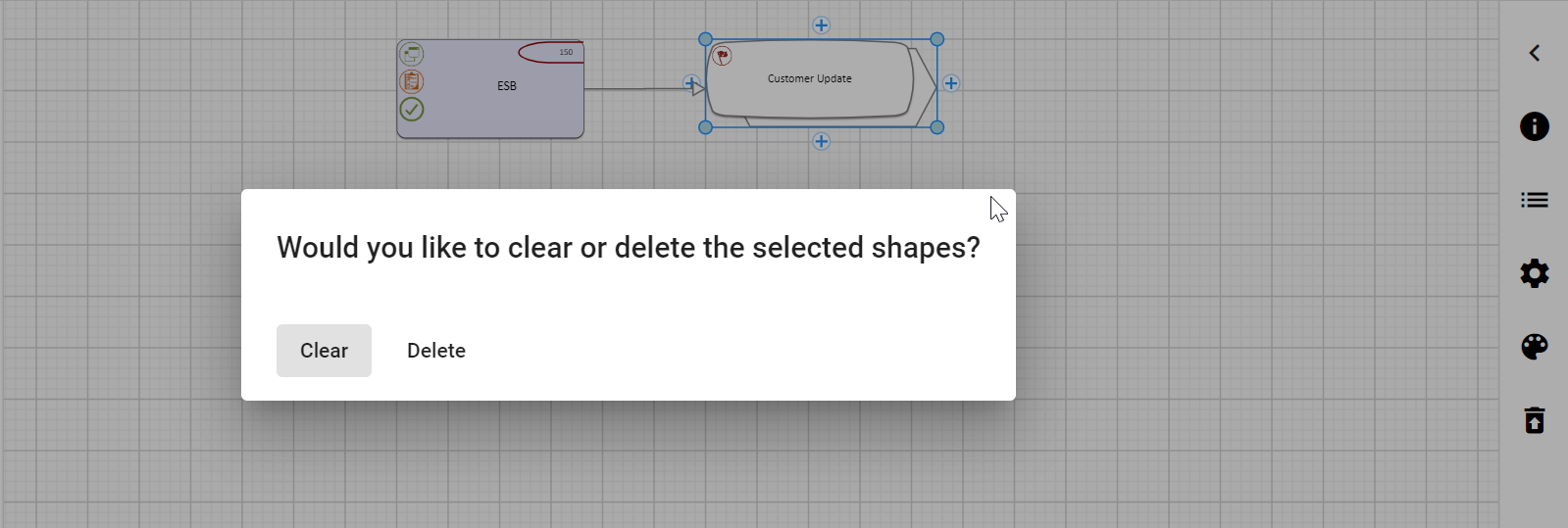
1.Select the shape you wish to Clear.
2.Press the Delete button on your computer's keyboard.
3.Confirm to Clear.
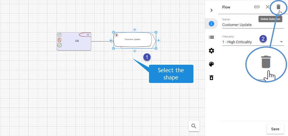
To Delete a Shape:
When you choose to Delete a shape, it removes the shape from the diagram, and when published will remove the object representing from the model too.
1.Select the shape you wish to Delete.
2.Click on 
Or
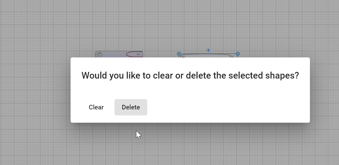
1.Select the shape you wish to Delete.
2.Press the Delete button on your computer's keyboard.
3.Confirm to Delete.
|
|
If a shape is deleted, any connector associated with the object shape also gets deleted. |
|
|
When object shapes are deleted using the Delete option, it adds the item to the Trash can icon called Deleted Objects on the right-hand pane. |
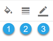
Adding Background Colors and Borders to the Shapes
Every Shape from the Palette has a definite background color, border size, and border color.
You can format the shape by
1.Background Color of the shape.
2.Border Size to the shape.
3.Border color to the shape.
|
|
Some shapes may have Region shapes and Region formatting which overrides these styles such that the style options will not work. |
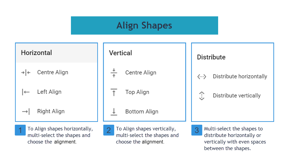
Aligning Shapes
Object shapes in the Web Modeler editor can be aligned using Align Nodes placed on the toolbar.
Object shapes can be aligned to the Left, Right, and Center horizontally, and also Top, Bottom, and Center vertically, which can also be evenly Distributed Horizontally or Vertically.
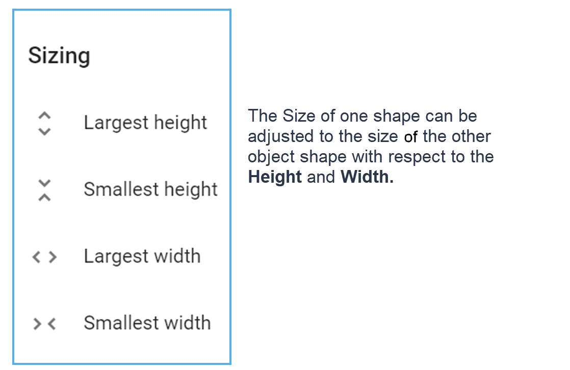
Resizing Shapes to match others
In the Web Modeler Editor, the object shape can be adjusted to the height and width of the other shape using Resize Nodes.
Move Shapes from Back and Front
In the diagram, if one shape is put on top of another, it may conceal the other.
Move To Back and Move To Front buttons help to show/Hide the object shape.
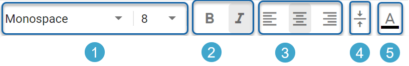
Text Formatting and Fonts
The Title of Object shapes can be formatted according to:
1.Font and its Font Size
2.Text in Bold, and Italic
3.Text alignment to Left, Center, and Right.
4.Vertical Alignment.
5.Text Color.
|
|
Some shapes may have Region shapes and Region formatting which overrides these styles such that the style options will not work. |