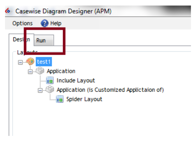
The run mode allows you to generate the diagrams depending on the configurations you have selected. When your diagram layout is correct, the run mode tab will appear next to the Design tab.
You can click on it in order to view the run mode.
|
|
Notice that depending on your design output type (single or group), the run mode varies. |
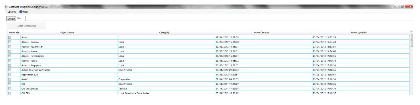
The run mode objects which are displayed depend on the Primary object selected.
Run Mode for Single Output Type
In the single mode output, a diagram will be created for each primary object you will select.
You can select an object by checking the Generate column (1st column).
When selected, the selected row’s state column will change, below the lists of the available states:
|
State |
Description |
|
Waiting for generation |
The row has been correctly selected, when ready you can then start the generation |
|
Generation in progress |
The diagram is under generation |
|
Generated |
The diagram has been generated; it can be open using the “Open Diagram” column. |
|
Clearing joiners & shapes |
The diagram has been opened and is being cleared, this take time depending on the number of shapes and joiners you have on the diagram. |
Once at least one object is selected, you will be able to use the “Start Generation” button and start the generation of the diagram(s).
When a generation finishes, the name of the diagrams appears in the “Open Diagram” column, which should be the last column. You may then click once (like a hypertext link in your browser) and the diagram will open in Modeler.
Run Mode for Group Output Type
In the group mode for the group output type, all the objects you are going to select will be displayed on the diagram.
You can select an object by checking the Generate column (1st column).
Once you have selected at least one object, you can then use the “Start Generation” button to create the diagram.
When the generation starts, a new button appears labeled “Generation under progress”.
When the diagram is generated the button changes to “Open the Diagram”, if you click it, the diagram will open in Modeler.
You can go back at any time to the Design mode, and return, and your selected items will remain checked.
Related Items
Batch Generation of Automatic Diagrams
The diagram designer generation can be automated. You first need to create your diagram design layout, make sure it’s working correctly by running it manually. Once checked you will be able to prepare the automatic execution.
To start configuring the batch mode:
1.Launch the “CMD” tool
2.Browse to your Diagram Designer installation directory
3.Launch the following command
DiagramDesigner.exe -h
The following usage will appear:
DiagramDesigner.exe -connection <connection_to_database> -model <model_filename>
-username <username> -password <password> -id <item_id>
Below details the arguments available:
|
Argument Key |
Description |
|
-connection |
The name of your connection used to connect Corporate Exchange |
|
-model |
The filename of the model you are going to use |
|
-username |
The Username to connect Corporate Modeler Suite |
|
-password |
The password associated with the username, leave “” if the password is empty |
|
-id |
The id of the design layout, accessible through the properties of the design layout which is available in the Diagram Designer Object Type |
|
|
Notice that you can use double quotes around your arguments if required. |
Related Items
The Diagram Designer logs some information depending on the level of log requested.
This level can be configured in the DiagramDesigner.exe.config file which is located next to the DiagramDesigner.exe application.
Values can be INFO or DEBUG.
Related Items
Batch Generation of Automatic Diagrams
Additional Layouts