|
Working with Connector Lines
The lines which associate the two objects in the diagram are called Connector Lines.

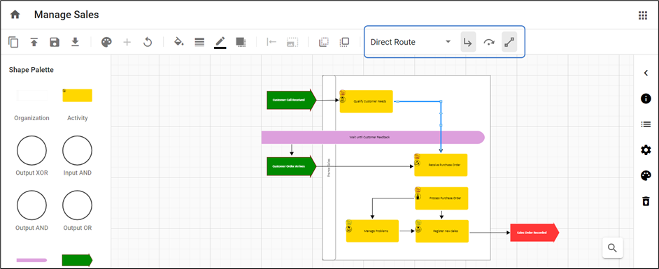
Double-click on the line, then the options for connector lines are shown on the toolbar.

Lines can be applied in two ways:
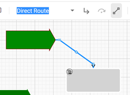
1.Direct Route – connects the objects using the shortest path.
2.Avoid Route – connects the objects avoiding the other objects in the diagram structure.
Lines are of three types are available to connect the objects:
1.Orthogonal Lines – Orthogonal Lines are when the line appears with right angles in order to connect the two objects when it cannot be drawn horizontally or vertically.
This line is available only under Direct Route and will be disabled for Avoid Route.
|
Orthogonal Off |
Orthogonal On |
|

|

|
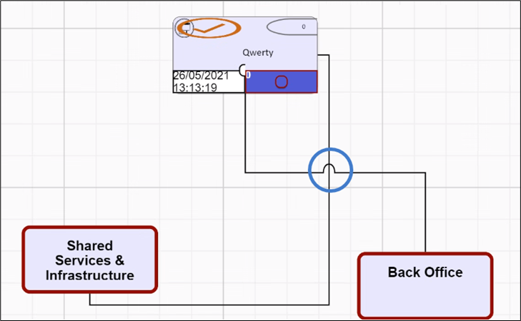
2. Jump Lines – Jump Lines are when one connecting line passes over another, and it appears with an arc over it.
This button is used in conjunction with the orthogonal lines button. If an orthogonal line is off for a particular line, then the jump line button is disabled.

Jump is a property of an individual line, so if the lines cross and neither have the jump property then they look like straight lines passing through one another. Jump lines will be seen if both lines have jump property.
3. Lock/Unlock Link Port – Link Ports can be Locked or Unlocked. To lock them, either press the button or move the connection point (port) of the line, around the shape. When you select a location to port the line to the shape, it will become locked. If you want the Diagrammer to automatically reposition the port, select the line, and press the unlock button, to release the lock.
Locking the link ports helps to keep the specific connection point when the shapes are moved around the canvas.
|