
NDMP
NDMP
The DR Series system VTL container type is designed to work seamlessly with the NDMP protocol.
iSCSI
iSCSI
iSCSI or Internet Small Computer System Interface is an Internet Protocol (IP)-based storage networking standard for storage subsystems. It is a carrier protocol for SCSI. SCSI commands are sent over IP networks by using iSCSI. It also facilitates data transfers over intranets and to manage storage over long distances. iSCSI can be used to transmit data over LANs or WANs.
In iSCSI, clients are called initiators and SCSI storage devices are targets. The protocol allows an initiator to send SCSI commands (CDBs) to the targets on remote servers. It is a storage area network (SAN) protocol, allowing organizations to consolidate storage into data center storage arrays while providing hosts (such as database and web servers) with the illusion of locally attached disks. Unlike traditional Fibre Channel, which requires different cabling, iSCSI can be run over long distances using existing network infrastructure.
Fibre channel
Fibre channel
Understanding the DR Series system hardware and data operations
Understanding the DR Series system hardware and data operations
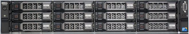
The DR Series system hardware consists of a total of 14 drives. Two of these drives are 2.5-inch drives that are configured as a Redundant Array of Independent Disks (RAID) 1 on the RAID Controller, and this is considered to be volume 1. On the DR4000 system, these drives are internal; while in the DR4100, DR6000, DR4300e core and standard, DR4300, and DR6300 systems, these drives are accessible from the rear of the appliance. The data that is being backed up is stored on the 12 virtual disks that reside on the DR Series system. The DR Series system also supports additional storage in the form of external expansion shelf enclosures (see the DR Series Expansion Shelf section in this topic). The hot-swappable data drives that are attached to the RAID controller are configured as:
Figure 1. DR Series System Drive Slot Locations
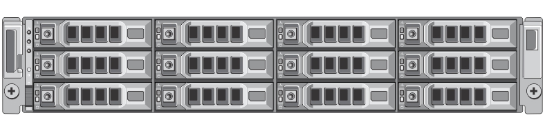
DR Series expansion shelf
Figure 2. DR Series System Expansion Shelf (MD1200) Drive Slot Locations
Understanding the process for adding a DR Series expansion shelf
The process for adding an expansion shelf requires the following: