Chat now with support
Chat with Support

DR Series DR6300 - Owner's Manual

DR6300 system overview Technical specifications Initial system setup and configuration Pre-operating system management applications
Options to manage the pre-operating system applications System Setup Dell Lifecycle Controller Boot Manager PXE boot
Installing and removing system components
Safety instructions Before working inside your system After working inside your system Recommended tools Front bezel (optional) System cover Cooling shroud Cooling fans Cooling-fan assembly System memory Processors and heat sinks PCIe card holder Cable retention bracket Integrated storage controller card Expansion cards and expansion card riser Internal dual SD module (optional) Network daughter card Internal USB memory key (optional) System battery Power supply units (PSU) System board Trusted Platform Module Hard drives Hard drive backplane SD vFlash card (optional) Control panel assembly
Using system diagnostics Jumpers and connectors Troubleshooting your system

Cooling-fan assembly

The cooling fan assembly is an essential part of a server’s cooling system. It ensures that the key components of the server such as the processors, hard drives, and memory get adequate air circulation to keep them cool. A failure in the server’s cooling system can result in the server overheating and may lead to damage.

Removing the cooling fan assembly

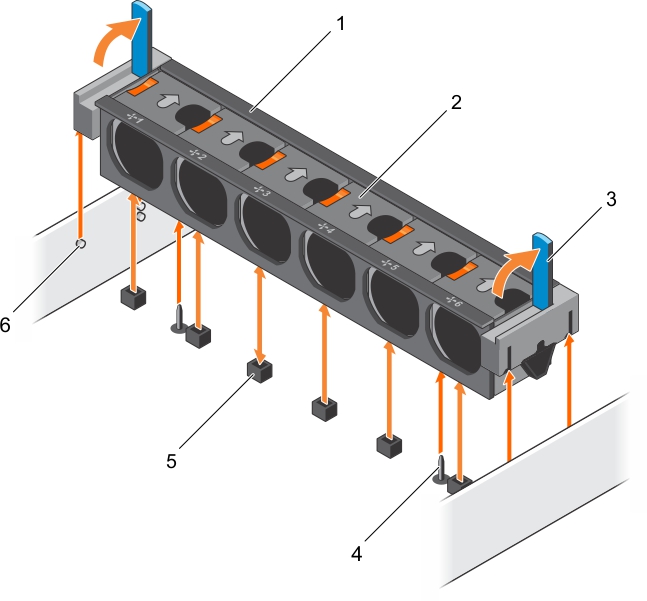
This figure shows removing the cooling fan assembly.

Installing the cooling fan assembly

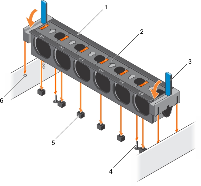
This shows installing the cooling fan assembly

Follow the procedure listed in the After working inside your system section.

System memory

Your system supports DDR4 registered DIMMs (RDIMMs). System memory holds the instructions that are executed by the processor.

Memory bus operating frequency can be 1866 MT/s, 2133 MT/s, or 2400 MT/s depending on the following factors:

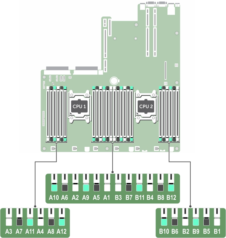
Your system contains 24 memory sockets split into two sets of 12 sockets, one set per processor. Each 12-socket set is organized into four channels. In each channel, the release tabs of the first socket are marked white, the second socket black, and the third socket green.

Figure 16. Memory socket locations

This figure helps in locating memory sockets.

Memory channels are organized as follows:

Table 29. Memory channels

Processor

Channel 0

Channel 1

Channel 2

Channel 3

Processor 1

Slots A1, A5, and A9

Slots A2, A6, and A10

Slots A3, A7, and A11

Slots A4, A8, and A12

Processor 2

Slots B1, B5, and B9

Slots B2, B6, and B10

Slots B3, B7, and B11

Slots B4, B8, and B12

The following table shows the memory populations and operating frequencies for the supported configurations:

Table 30. Memory population

DIMM Type

DIMMs Populated/Channel

Voltage

Operating Frequency (in MT/s)

Maximum DIMM Rank/Channel

RDIMM

1

1.2 V

2133, 1866, 1600, 1333

Dual rank or single rank

2

2133, 1866, 1600, 1333

Dual rank or single rank

3

1866, 1600, 1333

Dual rank or single rank

Related Documents

The document was helpful.

Select Rating

I easily found the information I needed.

Select Rating