暂时无法在支持网站上提交享有定期维护的产品表单。 如果您需要我们立即提供帮助,请与技术支持部门联系。 对于由此给您带来的不便,我们深表歉意。
获得即时帮助
完成注册
登录
请求定价
联系销售人员
您已选择一个产品捆绑包。 您能否选择单个产品以便我们更好地满足您的请求。 *
技术支持工程师目前正忙,无法回应您的消息。 如果需要即时服务,请通过我们的服务请求表提交请求。
以下文章可根据您的描述解决您的问题。
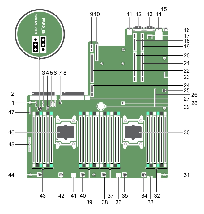
Figure 85. System board jumpers and connectors
Table 36. System board connectors and jumpers
Item
Connector
Description
1
J_BP_SIG1
Backplane signal connector 1
2
J_PS_2
PSU 2 connector
3
J_BP_SIG0
Backplane signal connector 0
4
J_BP0
Backplane power connector 0
5
J_SATA_CD
Optical drive SATA connector
6
J_SATA_TBU
Tape backup unit SATA connector
7
J_TBU
Tape backup unit power connector
8
J_PS_1
PSU 1 connector
9
J_IDSDM
Internal dual SD module connector
10
J_NDC
Network daughter card connector
11
J_USB
USB port
12
J_VIDEO_REAR
Video connector
13
J_COM1
Serial connector
14
J_IDRAC_RJ45
iDRAC8 connector
15
J_CYC
System identification connector
16
CYC_ID
System identification button
17
J_TPM_MODULE
Trusted Platform Module connector
18
J_RISER_2AX
Riser 3 connector
19
J_RISER_1AX
Riser 1 connector
20
J_RISER_2BX
Riser 2 connector
21
J_RISER_1BX
22
J_RISER_3AX
23
J_QS
Quick Sync bezel connector
24
J_RISER_3BX
25
J_SATA_B
Internal SAS connector
26
J_STORAGE
Mini PERC connector
27
J_USB_INT
Internal USB port
28
J_SATA_A
29
BAT
Battery connector
30
CPU 2
Processor 2 socket
31
J_BP3
Backplane power connector 3
32
B10, B6, B2, B9, B5, B1
Memory module sockets
33
J_BP_SIG2
Backplane signal connector 2
34
J_FAN2U_6
Cooling fan connector
35
J_FAN2U_5
36
J_BP2
Backplane power connector 2
37
B3, B7, B11, B4, B8, B12
38
J_FAN2U_4
39
A10, A6, A2, A9, A5, A1
40
J_FAN2U_3
41
J_BP1
Backplane power connector
42
J_FAN2U_2
43
A3, A7, A11, A4, A8, A12
44
J_FAN2U_1
45
J_CTRL_PNL
Control panel signal connector
46
CPU 1
Processor 1 socket
47
J_FP_USB
Front panel USB port
The software security features of the system include a system password and a setup password. The password jumper enables these password features or disables them and clears any password(s) currently in use.
The existing passwords are not disabled (erased) until the system boots with the jumper on pins 2 and 4. However, before you assign a new system and/or setup password, you must move the jumper back to pins 4 and 6.
If you boot the system to the BIOS boot mode after installing an operating system from the UEFI Boot Manager, the system stops responding. To avoid this issue, you must boot to the same boot mode in which you installed the operating system.
For all other startup issues, note the system messages that appear on the screen.
您可以在附属支持站点上查找适用于戴尔*产品*的在线支持帮助。单击“继续”,转至适用于*产品*的正确支持内容和帮助。
The document was helpful.
选择评级
I easily found the information I needed.
© 2024 Quest Software Inc. ALL RIGHTS RESERVED. 使用条款 隐私 Cookie Preference Center
Quest Software门户不再支持IE 8、9和10,建议将您的浏览器升级到最新版本的Internet Explorer或Chrome。
要升级到IE 11,请单击此处
要升级到Chrome,请单击此处
如果继续使用IE 8、9和10,您将无法充分利用我们所有出色的自助服务功能。