|
4. |
|
|
|||
|
|
|||
|
|
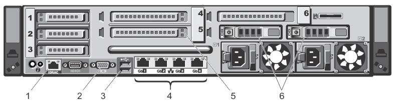
Connects USB devices to the system. The ports are USB 2.0-compliant. | ||
|
|
|||
|
8. |
|
|
|||
|
|
|||
|
|
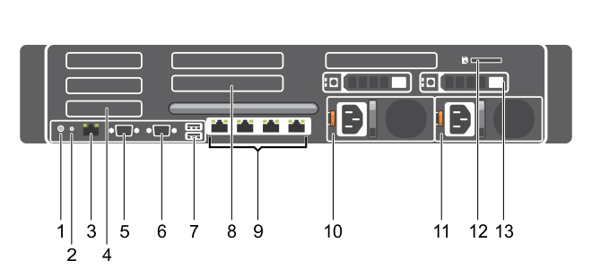
Connects USB devices to the system. The ports are USB 2.0-compliant. | ||
|
|
Four integrated 10/100/1000 NIC connectors, or four integrated connectors that include: | ||
|
12. |
|
• |
Default username: root |
|
• |
Default password: calvin |
|
• |
Default static IP address: 192.168.0.120 |
For information about configuring the iDRAC, see the Dell RACADM Reference Guides at support.dell.com/manuals and the topic, Accessing iDRAC6/iDRAC7 Using RACADM.
When the DR Series System splash screen is displayed, you are ready to begin initialization using the DR Series system CLI logon process. For more information, see Logging in and Initializing the DR Series System.
The logon values you can use for making iDRAC connections are:
|
• |
Default username: root |
|
• |
Default password: calvin |
|
• |
Default static IP address: 192.168.0.120 |
For more information, see the RACADM Reference Guides for iDRAC, the Integrated Dell Remote Access Controller 6 (iDRAC6) User Guide, or the Integrated Dell Remote Access Controller 7 (iDRAC7) User Guide that are available at support.dell.com/manuals.
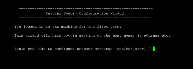
When you initialize the system you will log on to the DR Series system CLI by using a local console KVM (keyboard-video monitor) connection or an iDRAC connection. (For more information, see the topic, Local Console Connection, or iDRAC Connection.) You will then configure your system network settings by using the Initial System Configuration Wizard as described in the steps below.
To log on and initialize the DR Series system, complete the following steps:
|
2. |
|
3. |
At the administrator@<system_name> password: prompt, type the default administrator password (St0r@ge!), and press <Enter>. |
|
4. |
|
NOTE: When you select static IP addressing, you are prompted to type the static IP address (for example, you could use the default IP, 10.77.88.99) for the system, and press <Enter>. If your network supports the use of DHCP, type yes at the DHCP prompt, press <Enter>, and respond to any prompts. |
|
8. |
|
10. |
|
11. |
To change the default host name (for example, the serial number of the DR Series hardware appliance), type y (for yes) and press <Enter>. |
|
12. |
|
13. |
If you want to change any of these settings, type n (for no), and press <Enter>. Modify the settings as needed, and press <Enter>. |
|
14. |
You are now ready to log in to the system using the DR Series system GUI.