Chat now with support
Chat mit Support

DR Series DR4300 - Owner's Manual

DR4300 system overview Technical specifications Initial system setup and configuration Pre-operating system management applications
Options to manage the pre-operating system applications System Setup Dell Lifecycle Controller Boot Manager PXE boot
Installing and removing system components
Safety instructions Before working inside your system After working inside your system Recommended tools Front bezel (optional) System cover Cooling shroud Cooling fans Cooling-fan assembly System memory Processors and heat sinks PCIe card holder Cable retention bracket Integrated storage controller card Expansion cards and expansion card riser Internal dual SD module (optional) Network daughter card Internal USB memory key (optional) System battery Power supply units (PSU) System board Trusted Platform Module Hard drives Hard drive backplane SD vFlash card (optional) Control panel assembly
Using system diagnostics Jumpers and connectors Troubleshooting your system

Hard drive indicator codes

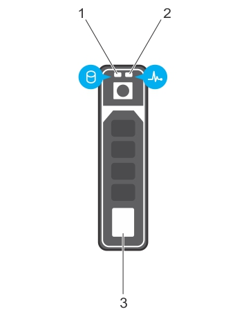
Each hard drive carrier has an activity indicator and a status indicator. The indicators provide information about the current status of the hard drive. The activity LED indicates whether hard drive is currently in use or not. The status LED indicates the power condition of the hard drive.

Figure 3. Hard drive indicators

This figure shows hard drive indicators.

Table 4. Hard drive indicator codes

Drive-status indicator pattern (RAID only)

Condition

Flashes green twice per second

Identifying drive or preparing for removal.

Off

Drive ready for insertion or removal.

Flashes green, amber, and then turns off

Predicted drive failure

Flashes amber four times per second

Drive failed

Flashes green slowly

Drive rebuilding

Steady green

Drive online

Flashes green for three seconds, amber for three seconds, and then turns off after six seconds

Rebuild stopped

NIC indicator codes

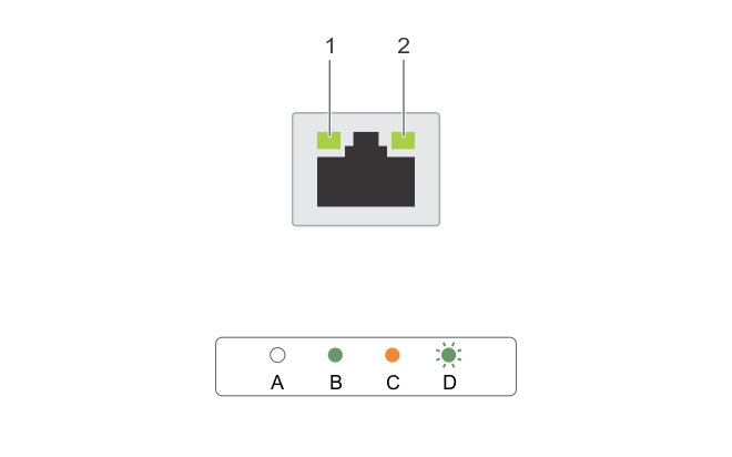
Each NIC on the back panel has an indicator that provides information about the network activity and link status. The activity LED indicates whether the NIC is currently connected or not. The link LED indicates the speed of the connected network.

Figure 4. NIC indicators

This figure shows NIC indicator codes.

Table 5. NIC indicators

Convention

Status

Condition

A

Link and activity indicators are off

The NIC is not connected to the network.

B

Link indicator is green

The NIC is connected to a valid network at its maximum port speed (1 Gbps or 10 Gbps).

C

Link indicator is amber

The NIC is connected to a valid network at less than its maximum port speed.

D

Activity indicator is flashing green

Network data is being sent or received.

Power supply unit indicator codes

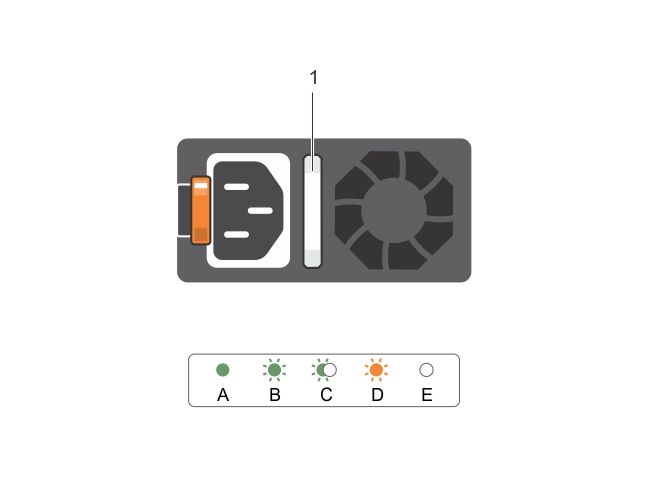
AC power supply units (PSUs) have an illuminated translucent handle that serves as an indicator and DC PSUs have an LED that serves as an indicator.  The indicator shows whether power is present or a power fault has occurred.

Figure 5. AC PSU status indicator

This figure shows AC PSU status indicator/handle.

Table 6. AC PSU status indicators

Convention

Power indicator pattern

Condition

A

Green

A valid power source is connected to the PSU and the PSU is operational.

B

Flashing green

When the firmware of the PSU is being updated, the PSU handle flashes green.

C

Flashing green and turns off

When hot-adding a PSU, the PSU handle flashes green five times at 4 Hz rate and turns off. This indicates a PSU mismatch with respect to efficiency, feature set, health status, and supported voltage.

D

Flashing amber

Indicates a problem with the PSU.

E

Not lit

Power is not connected.

iDRAC Direct LED indicator codes

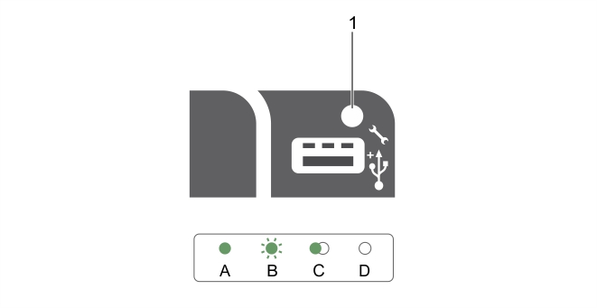
The iDRAC Direct LED indicator lights up to indicate that the port is connected and is being used as a part of the iDRAC subsystem.

Figure 6. iDRAC Direct LED indicator

This figure shows the iDRAC Direct status indicator.

The iDRAC Direct LED indicator table describes iDRAC Direct activity when configuring iDRAC Direct by using the management port (USB XML Import).

Table 7. iDRAC Direct LED indicators

Convention

iDRAC Direct LED indicator pattern

Condition

A

Green

Turns green for a minimum of two seconds to indicate the start and end of a file transfer.

B

Flashing green

Indicates file transfer or any operation tasks.

C

Green and turns off

Indicates that the file transfer is complete.

D

Not lit

Indicates that the USB is ready to be removed or that a task is complete.

The following table describes iDRAC Direct activity when configuring iDRAC Direct by using your laptop and cable (Laptop Connect):

Table 8. iDRAC Direct LED indicator patterns

iDRAC Direct LED indicator pattern

Condition

Solid green for two seconds

Indicates that the laptop is connected.

Flashing green (on for two seconds and off for two seconds) 

Indicates that the laptop connected is recognized.

Turns off

Indicates that the laptop is unplugged.

Verwandte Dokumente

The document was helpful.

Bewertung auswählen

I easily found the information I needed.

Bewertung auswählen