Chat now with support
Chat with Support

DR Series Software 3.2.0.2 - Administrator Guide

Introduction to the DR Series System Documentation Understanding the DR Series System Setting Up the DR Series System Hardware Configuring the DR Series System Settings Managing DR Series Storage Operations Monitoring the DR Series System Using Global View Using the DR Series System Support Options Configuring and Using Rapid NFS and Rapid CIFS Configuring and Using Rapid Data Access with Dell NetVault Backup and with Dell vRanger Configuring and Using RDA with OST
Understanding RDA with OST Guidelines Terminology Supported RDA with OST Software and Components Best Practices: RDA with OST and the DR Series System Setting Client-Side Optimization Configuring an LSU Installing the RDA with OST Plug-In Configuring DR Series System Information Using NetBackup Backing Up Data From a DR Series System (NetBackup) Using Backup Exec With a DR Series System (Windows) Understanding the OST CLI Commands Understanding RDA with OST Plug-In Diagnostic Logs Collecting Diagnostics Using a Linux Utility Guidelines for Gathering Media Server Information
Configuring and Using VTL Configuring and Using Encryption at Rest Troubleshooting and Maintenance Supported Ports in a DR Series System Getting Help

Connections for Initializing a DR Series System

Connections for Initializing a DR Series System

There are two supported methods for connecting to the DR Series system for logging in and performing the initial system configuration via the DR Series system CLI:

Local console connection: this is a local access connection made between a local workstation and the DR Series system (with one connection made to a USB keyboard port on the DR Series front/rear chassis, and a second connection made to the VGA monitor port on the DR Series system rear chassis. (See Figure 3 for locations in the DR Series System Rear Chassis Port Locations in the Local Console Connection.)
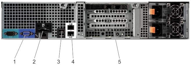
iDRAC connection: this is a remote access connection made between an integrated Dell Remote Access Controller (iDRAC) and the dedicated management port on the DR Series system rear chassis. (See Figure 3 for locations in the DR Series System Rear Chassis Port Locations in the Local Console Connection.)

Initializing the DR Series System

Initializing the DR Series System

Before you can start using the DR Series system graphical user interface (GUI) for the first time, you must properly initialize the system. To initialize the DR Series system, complete the following:

1.
2.

The Initial System Configuration Wizard lets you configure the following network settings to complete a first-time initialization of your system:

Default IP Address and Subnet Mask Address

Default IP Address and Subnet Mask Address

This topic lists the following default address values that can be used for initialization of a DR Series system:

IP address—10.77.88.99

There are two key factors related to default address values and initializing a DR Series system:

If the network where the system will reside does not have or does not support DHCP, then the DR Series system can use the default IP (10.77.88.99) and subnet mask (255.0.0.0) addresses provided for initialization. If the network where the system will reside does not have or support reserving an IP address for the MAC address of the NICs in the DHCP server, then DHCP assigns an arbitrary IP address that is unknown (and which is unusable by you) during initialization.

As a result, if your network does not support DHCP or if you cannot reserve an IP address for the specific MAC addresses of the DHCP network interface cards (NICs), then Dell recommends that you use the local console connection method and the Initial System Configuration Wizard.

NOTE: If you have not run the Initial System Configuration Wizard on one (or more) DR Series system(s) being installed into the same network, there is a potential that the system (or systems) may come up with the same default IP address (10.77.88.99). The default IP address is not user-configurable and it can potentially result in becoming a duplicate IP address in the case of multiple systems.

Initialization issues could include when a network has had a network power outage, the DHCP server in the network is misconfigured, or if the Initial System Configuration Wizard has never been run.

If your network does not accept the default subnet mask address (255.0.0.0), you can establish a connection between the DR Series system and a laptop workstation. In this case, make sure that you connect using SSH, and use the default IP address to run the Initial System Configuration Wizard.

If you are using a known static IP address, you can skip running the Initial System Configuration Wizard, and directly configure the DR Series system using its user interface.

To configure the DR Series system, select System Configuration > Networking, and configure the network settings as desired. For more information, see Configuring Networking Settings.

Local Console Connection

Local Console Connection

To configure a local console connection, you must make the following two rear chassis cable connections:

VGA port and your video monitor

To make local console cable connections for the DR Series system appliance, complete the following:

1.
(DR4000 system) Locate the VGA monitor port and the USB ports on the back of your system. See Figure 3 for the VGA and USB port locations and complete steps 1 to 4. For the DR4100/DR6000 system, skip to step 5.
2.
3.
4.
Figure 6. DR4000 System Rear Chassis Port Locations

The figure shows the DR4000 system rear chassis port and connector locations.

Item

Indicator, Button, or Connector

Icon

Description

1

Video connector

Connects a VGA display to the system.

2

iDRAC6 Enterprise port

Dedicated management port for the iDRAC6 Enterprise card.

3

USB connectors (2)

Connects USB devices to the system. The ports are USB 2.0-compliant.

4

Ethernet connectors (2)

Embedded 10/100/1000 NIC connectors.

5

Ethernet Connectors (2) on expansion card

1-GbE/10-GbE/10-GbE SFP+ Ethernet Port

To make local console cable connections for the DR4100 system appliance, complete the following:

5.
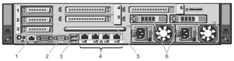
(DR4100/DR6000 system) Locate the VGA monitor port and the USB ports on the back of your system. See Figure 3 for the VGA and USB port locations and complete steps 5 to 8.
6.
7.
8.
Figure 7. DR4100/DR6000 System Rear Chassis Port Locations

The figure shows the DR4100 system rear chassis port and connector locations.

Item

Indicator, Button, or Connector

Icon

Description

1

iDRAC7 Enterprise port

Dedicated management port for the iDRAC7 Enterprise card (port is available only if an iDRAC7 Enterprise license is installed on your system).

2

Video connector

Connects a VGA display to the system.

3

USB connectors (2)

Connects USB devices to the system. The ports are USB 2.0-compliant.

4

Ethernet connectors (4)

Four integrated 10/100/1000 NIC connectors, or four integrated connectors that include:

5

PCIe expansion card slots (3)

Connect up to three full-height PCI Express expansion cards

6

Hard drives (2)

Provides two hot-swappable 2.5-inch hard drives

Related Documents

The document was helpful.

Select Rating

I easily found the information I needed.

Select Rating