지금 지원 담당자와 채팅
지원 담당자와 채팅

DR Series Software 4.0.0.3 - Administration Guide

Introducing the DR Series system documentation Introducing the DR Series system Setting up the DR Series system Configuring the DR Series system settings Managing containers Managing replications Monitoring the DR Series system Using GlobalView Configuring and using Rapid NFS and Rapid CIFS Configuring and using Rapid Data Access with NetVault Backup and with vRanger Configuring and using RDA with OST
Understanding RDA with OST Guidelines Terminology Supported RDA with OST software and components Best Practices: RDA with OST and the DR Series System Setting client-side optimization Configuring an LSU Installing the RDA with OST plug-in Configuring DR Series system information using NetBackup Backing Up Data From a DR Series System (NetBackup) Using Backup Exec with a DR Series system (Windows) Understanding the OST CLI commands Understanding RDA with OST Plug-In Diagnostic Logs Collecting Diagnostics Using a Linux Utility Guidelines for Gathering Media Server Information
Configuring and using VTL Configuring and Using Encryption at Rest Support, maintenance, and troubleshooting Supported Ports in a DR Series System

Understanding DR Series system hardware expansion shelf cabling

Understanding DR Series system hardware expansion shelf cabling

The DR Series system hardware appliance is capable of supporting additional storage capacity by connecting Dell PowerVault MD1200 (DR4000, DR4100, DR6000) or Dell PowerVault MD1400 (DR4300e core and standard, DR4300, DR6300) data storage expansion shelf enclosures. The expansion shelf enclosure contains 12 physical disks that provide additional data storage capacity for a basic DR Series system. For the expansion unit limits and supported capacities, see the DR Series System Interoperability Guide.

As an example, this section and the following figures display the recommended method for cabling between the DR Series system’s PERC controller card to the appropriate connectors on the rear of a Dell PowerVault MD1200 expansion shelf enclosure.

Make sure that the Dell PowerVault MD1200 front panel selector switch is set to its Unified mode (with the switch set to its “up” position, indicated by a single Volume icon). The first figure below shows the SAS In ports on the Enclosure Management Module (EMM) on the rear of the Dell MD1200. The next figure shows the recommended redundant path cabling configuration, which includes cable connections from both PERC H800 connectors on the DR4000 system (or the PERC H810 on a DR4100/DR6000 system) to the two SAS In ports on the EMM rear chassis of the Dell PowerVault MD1200.

If you plan on installing multiple expansion shelf enclosures, then the two SAS In ports on the rear chassis of the EMM on the additional enclosure are daisy-chained to the two SAS Out ports on the EMM rear chassis on the first enclosure. This is considered a redundant mode connection via the SAS In/Out connectors on the enclosures with the DR Series system appliance.

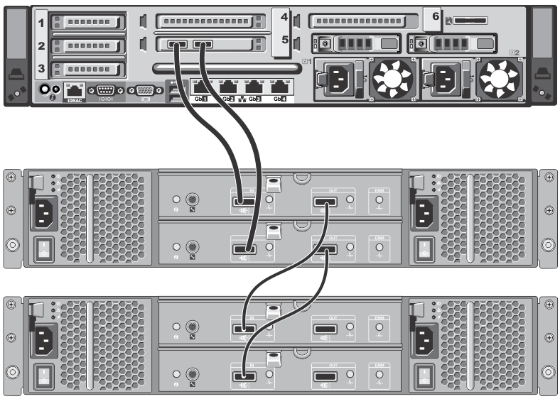
If you install multiple enclosures and cable them as described here, make sure to set the enclosure mode switch on the MD1200 front chassis to the top (unified mode) position. For more information, see the Dell PowerVault MD1200 and MD1220 Storage Enclosures Hardware Owner's Manual or the Dell Storage MD1400 Enclosures Hardware Owner’s Manual at dell.com/support/manuals.

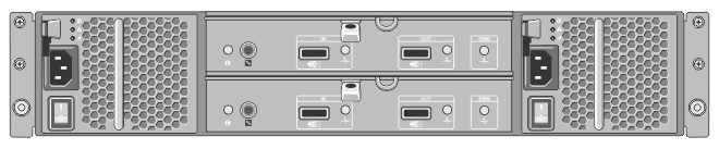
Figure 3. Dell PowerVault MD1200 Rear Chassis

This figure shows the rear chassis of the EMM on the MD1200 enclosure, with the two SAS In and two SAS Out ports.

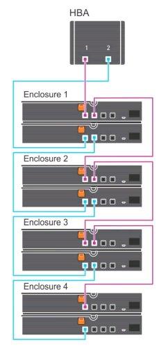
Figure 4. Unified Mode Daisy-Chained Redundant Path Dell PowerVault MD1200 Enclosures

This figure shows the PERC H810 connector cable connections between a DR4100 system rear chassis to the first expansion enclosure, and the cable connections from the first expansion enclosure to the second one using the SAS In/Out ports.

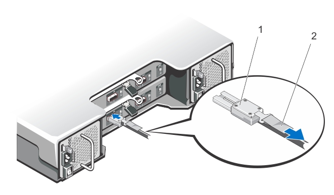
Figure 5. SAS Port and Cable Connections (Dell PowerVault MD1200 EMM)

This figure shows how an SAS cable connection is made to an SAS In/Out port: 1) SAS cable, and 2) cable pull-tab.

For the DR4300e core and standard, DR4300, and DR6300, the Dell Storage MD1400 expansion shelf enclosure is used for data storage expansion. The MD1400 has 4 ports in each controller or EMM; and, it is recommended to use ports 1 and 2 on the MD1400.

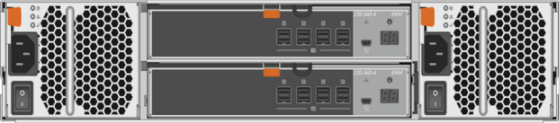
Figure 6. Dell Storage MD1400 Rear Chassis

This photograph shows the Dell Storage MD1400 rear chassis.

Figure 7. Daisy-Chained Redundant Path Dell Storage MD1400 Enclosures

This is an illustration of a daisy-chained redundant path for the Dell Storage MD1400 enclosures.

Supported software and hardware

Supported software and hardware

For a complete list of the latest supported software and hardware for the DR Series system, refer to the DR Series System Interoperability Guide. You can download this guide by visiting support.quest.com/dr-series, selecting your specific DR model and then navigating to Technical Documentation.

The DR Series System Interoperability Guide includes the following supported hardware and software categories:

Terminal emulation applications

To access the DR Series system command line interface (CLI), the following terminal emulation applications can be used:

Setting up the DR Series system

Setting up the DR Series system

You can interact with the DR Series system hardware using one of two supported methods: the system graphical user interface (GUI) accessed in a web browser or the command line interface (CLI) accessed by using a terminal emulator application (for example, PuTTY). Before you can interact with your system, you must first, however, ensure that the DR Series system is properly set up.

NOTE: The topics in this section apply to DR Series hardware systems. For information about setting up the virtual DR Series system, DR2000v, see the DR2000v Deployment Guide and the DR Series System Interoperability Guide. For more information on the DR Series system CLI commands, see the DR Series System Command Line Reference Guide.

Interacting with the DR Series system

Interacting with the DR Series system

You can interact with the DR Series system by using the system graphical user interface (GUI) in your web browser.

In the system GUI, you can configure your system as well as create and manage containers, which store your backup and deduplicated data. A data container is a shared file system that is imported using a client, and is accessible via file system or tape access protocols. For details, see Supported File System Protocols. The system GUI also provides real-time summary information for monitoring the status of the data capacity, storage savings, and the throughput of your data containers.

관련 문서

The document was helpful.

평가 결과 선택

I easily found the information I needed.

평가 결과 선택