Tchater maintenant avec le support
Tchattez avec un ingénieur du support

DR Series Software 3.2.0.2 - Administrator Guide

Introduction to the DR Series System Documentation Understanding the DR Series System Setting Up the DR Series System Hardware Configuring the DR Series System Settings Managing DR Series Storage Operations Monitoring the DR Series System Using Global View Using the DR Series System Support Options Configuring and Using Rapid NFS and Rapid CIFS Configuring and Using Rapid Data Access with Dell NetVault Backup and with Dell vRanger Configuring and Using RDA with OST
Understanding RDA with OST Guidelines Terminology Supported RDA with OST Software and Components Best Practices: RDA with OST and the DR Series System Setting Client-Side Optimization Configuring an LSU Installing the RDA with OST Plug-In Configuring DR Series System Information Using NetBackup Backing Up Data From a DR Series System (NetBackup) Using Backup Exec With a DR Series System (Windows) Understanding the OST CLI Commands Understanding RDA with OST Plug-In Diagnostic Logs Collecting Diagnostics Using a Linux Utility Guidelines for Gathering Media Server Information
Configuring and Using VTL Configuring and Using Encryption at Rest Troubleshooting and Maintenance Supported Ports in a DR Series System Getting Help

iSCSI

iSCSI

iSCSI or Internet Small Computer System Interface is an Internet Protocol (IP)-based storage networking standard for storage subsystems. It is a carrier protocol for SCSI. SCSI commands are sent over IP networks by using iSCSI. It also facilitates data transfers over intranets and to manage storage over long distances. iSCSI can be used to transmit data over LANs or WANs.

In iSCSI, clients are called initiators and SCSI storage devices are targets. The protocol allows an initiator to send SCSI commands (CDBs) to the targets on remote servers. It is a storage area network (SAN) protocol, allowing organizations to consolidate storage into data center storage arrays while providing hosts (such as database and web servers) with the illusion of locally attached disks. Unlike traditional Fibre Channel, which requires different cabling, iSCSI can be run over long distances using existing network infrastructure.

iSCSI is a low-cost alternative to Fibre Channel, which requires dedicated infrastructure except in FCoE (Fibre Channel over Ethernet). Note that the performance of an iSCSI SAN deployment can be degraded if not operated on a dedicated network or subnet

The VTL container type is designed to work seamlessly with the iSCSI protocol. For details, see the topic, Creating Storage Containers.

DR Series System Hardware and Data Operations

DR Series System Hardware and Data Operations

Data is stored and resides on the Dell DR Series DR4X00 and DR6X00 hardware appliance systems (two-rack unit (RU) appliances), which have DR Series system software pre-installed.

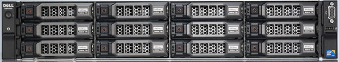
The DR Series system hardware consists of a total of 14 drives. Two of these drives are 2.5-inch drives that are configured as a Redundant Array of Independent Disks (RAID) 1 on the RAID Controller, and this is considered to be volume 1. On the DR4000 system, these drives are internal; while in the DR4100, DR6000, DR4300e, DR4300, and DR6300 systems, these drives are accessible from the rear of the appliance. The data that is being backed up is stored on the 12 virtual disks that reside on the DR Series system. The DR Series system also supports additional storage in the form of external expansion shelf enclosures (see the DR Series Expansion Shelf section in this topic). The hot-swappable data drives that are attached to the RAID controller are configured as:

The DR Series system supports RAID 6, which allows the appliance to continue read and write requests to the RAID array virtual disks even in the event of up to two concurrent disk failures, providing protection to your mission-critical data. In this way, the system design supports double-data drive failure survivability.

If the system detects that one of the 11 virtual drives has failed, then the dedicated hot spare (drive slot 0) becomes an active member of the RAID group. Data is then automatically copied to the hot spare as it acts as the replacement for the failed drive. The dedicated hot spare remains inactive until it is called upon to replace a failed drive. This scenario is usually encountered when a faulty data drive is replaced. The hot spare can act as replacement for both internal mirrored drives and the RAID 6 drive arrays.

Figure 1. DR Series System Drive Slot Locations

The figure shows the DR Series system drive slot locations.

Drive 0 (top)

Drive 3 (top)

Drive 6 (top)

Drive 9 (top)

Drive 1 (middle)

Drive 4 (middle)

Drive 7 (middle)

Drive 10 (middle)

Drive 2 (bottom)

Drive 5 (bottom)

Drive 8 (bottom)

Drive 11 (bottom)

DR Series Expansion Shelf

The DR Series hardware system appliance supports the installation and connection of Dell PowerVault MD1200 (for DR4000, DR4100, and DR6000) and Dell PowerVault MD1400 (for DR4300e, DR4300, and DR6300 systems) data storage expansion shelf enclosures. Each expansion shelf contains 12 physical disks in an enclosure, which provides additional data storage capacity for the basic DR Series system. The supported data storage expansion shelves can be added in a variety of capacities based on your DR Series system version; for details, see the Dell DR Series System Interoperability Guide.

The physical disks in each expansion shelf are required to be Dell-certified Serial Attached SCSI (SAS) drives, and the physical drives in the expansion shelf uses slots 1–11 configured as RAID 6, with slot 0 being a global hot spare (GHS). When being configured, the first expansion shelf is identified as Enclosure 1 (in the case where two enclosures are added, these would be Enclosure 1 and Enclosure 2). Adding an expansion shelf to support the DR Series system requires a license. For more information, see the topic, “Expansion Shelf Licenses.”

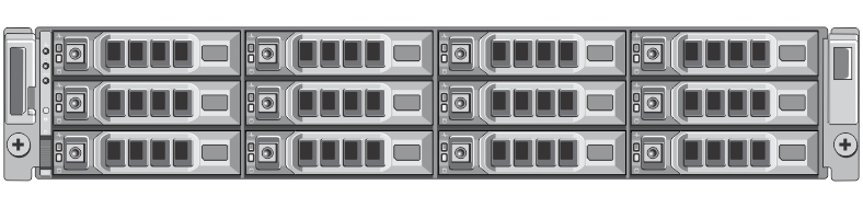
Figure 2. DR Series System Expansion Shelf (MD1200) Drive Slot Locations

The figure shows the DR Series system expansion shelf (MD1200) drive slot locations.

Drive 0 (top)

Drive 3 (top)

Drive 6 (top)

Drive 9 (top)

Drive 1 (middle)

Drive 4 (middle)

Drive 7 (middle)

Drive 10 (middle)

Drive 2 (bottom)

Drive 5 (bottom)

Drive 8 (bottom)

Drive 11 (bottom)

Understanding the Process for Adding a DR Series Expansion Shelf

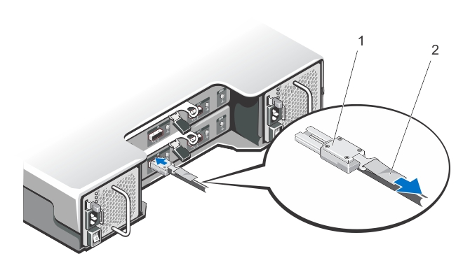
The process for adding an expansion shelf requires the following:

Supported Software and Hardware

Supported Software and Hardware

For a complete list of the latest supported software and hardware for the DR Series system, refer to the Dell DR Series System Interoperability Guide. You can download this guide by visiting dell.com/powervaultmanuals and selecting your specific DR Series system, which opens the product support page to view product documentation for your system.

The Dell DR Series System Interoperability Guide lists the following supported hardware and software categories:

Terminal Emulation Applications

To access the DR Series system command line interface (CLI), the following terminal emulation applications can be used:

DR Series Hardware System — Expansion Shelf Cabling

DR Series Hardware System — Expansion Shelf Cabling

The DR Series hardware system appliance is capable of supporting additional storage capacity by connecting Dell PowerVault MD1200 (DR4000, DR4100, DR6000) or Dell PowerVault MD1400 (DR4300e, DR4300, DR6300) data storage expansion shelf enclosures. The expansion shelf enclosure contains 12 physical disks that provide additional data storage capacity for a basic DR Series system. For the expansion unit limits and supported capacities, see the Dell DR Series System Interoperability Guide.

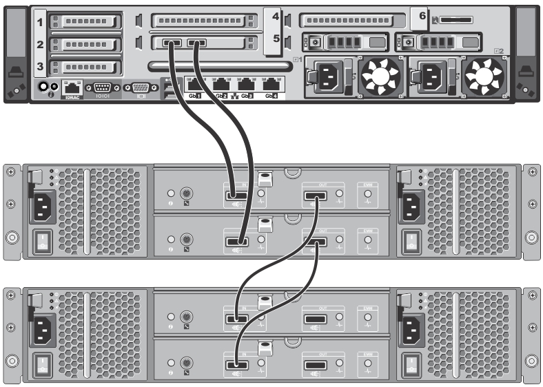
As an example, this section and the following figures, Figure 1 and Figure 2 display the recommended method for cabling between the DR Series system’s PERC controller card to the appropriate connectors on the rear of a Dell PowerVault MD1200 expansion shelf enclosure. This example applies to the DR4000, DR4100, and DR6000 systems. Note that for the DR4300e, DR4300, and DR6300, the MD1400 expansion shelf enclosure is used.

Make sure that the Dell PowerVault MD1200 front panel selector switch is set to its Unified mode (with the switch set to its “up” position, indicated by a single Volume icon). Figure 1 shows the SAS In ports on the Enclosure Management Module (EMM) on the rear of the Dell MD1200. Figure 2 shows the recommended redundant path cabling configuration, which includes cable connections from both PERC H800 connectors on the DR4000 system (or the PERC H810 on a DR4100/DR6000 system) to the two SAS In ports on the EMM rear chassis of the Dell PowerVault MD1200.

If you plan on installing multiple expansion shelf enclosures, then the two SAS In ports on the rear chassis of the EMM on the additional enclosure are daisy-chained to the two SAS Out ports on the EMM rear chassis on the first enclosure. This is considered a redundant mode connection via the SAS In/Out connectors on the enclosures with the DR Series system appliance.

If you install multiple enclosures and cable them as described here, make sure to set the enclosure mode switch on the MD1200 front chassis to the top (unified mode) position. For more information, see Dell PowerVault MD1200 and MD1220 Storage Enclosures Hardware Owner's Manual at dell.com/support/home.

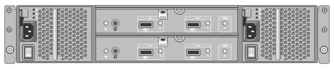
Figure 3. Dell PowerVault MD1200 Rear Chassis

This figure shows the rear chassis of the EMM on the MD1200 enclosure, with the two SAS In and two SAS Out ports.

Figure 4. Unified Mode Daisy-Chained Redundant Path Dell PowerVault MD1200 Enclosures

This figure shows the PERC H810 connector cable connections between a DR4100 system rear chassis to the first expansion enclosure, and the cable connections from the first expansion enclosure to the second one using the SAS In/Out ports.

Figure 5. SAS Port and Cable Connections (Dell PowerVault MD1200 EMM)

This figure shows how an SAS cable connection is made to an SAS In/Out port: 1) SAS cable, and 2) cable pull-tab.

1.
2.
Documents connexes

The document was helpful.

Sélectionner une évaluation

I easily found the information I needed.

Sélectionner une évaluation