
DR4300 system overview
DR4300 system overview
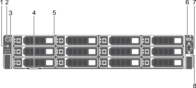
Front panel features and indicators
Figure 1. Dell DR4300 system front panel features and indicators
|
2. |
|
3. |
|
5. |
|
8. |
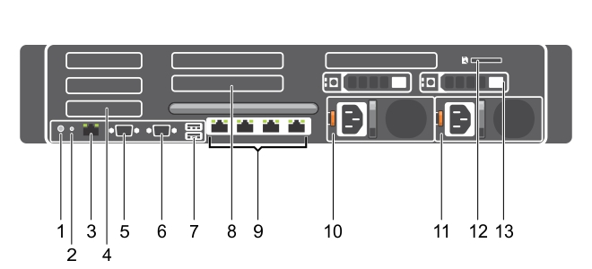
Back panel features
Figure 2. Back panel features
|
7. |
|
13. |
|
|
|||
|
Connects the optional system status indicator assembly through the optional cable management arm. | |||
|
|
|||
|
Enables you to connect up to 3 half-height PCI Express expansion cards. | |||
|
|
|||
|
|
|||
|
|
Enables you to connect USB devices to the system. The ports are USB 3.0-compliant. | ||
|
Enables you to connect up to 3 full-height PCI Express expansion cards. | |||
|
|
Four integrated 10/100/1000 Mbps Network Interface Card (NIC) connectors | ||
Diagnostic indicators on the front panel
|
|
The indicator turns solid blue if the system is in good health. |
||||
|
Check the System Event Log or system messages for the specific issue. For more information about error messages, see the Dell Event and Error Messages Reference Guide at Dell.com/openmanagemanuals > OpenManage software. | |||||
|
|
|||||
|
|
|||||
|
|
Ensure that none of the following conditions exist:
| ||||
|
|